
Distributed Infrastructure

Inactive Publication Date: 2014-06-19
BISCOTTI
View PDF7 Cites 23 Cited by
  • Summary
  • Abstract
  • Description
  • Claims
  • Application Information

AI Technical Summary

Benefits of technology

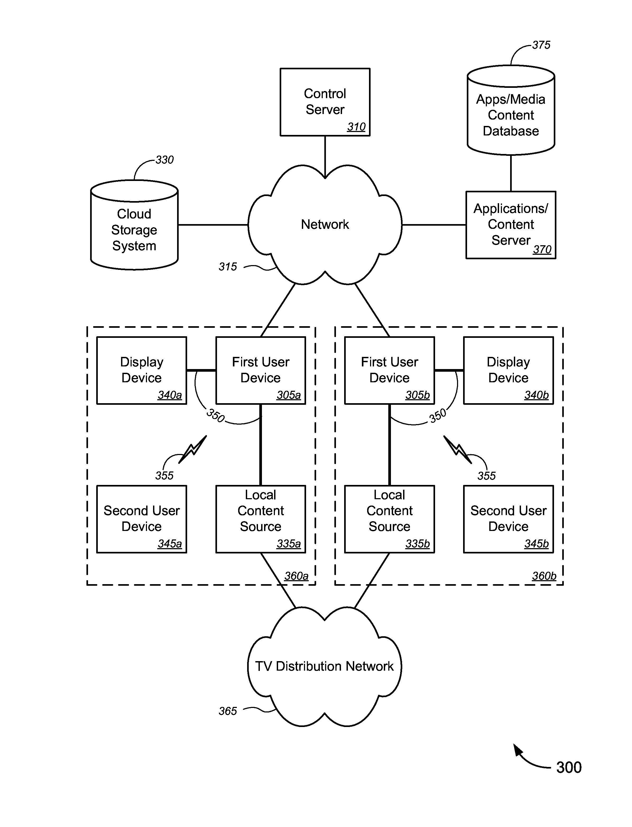
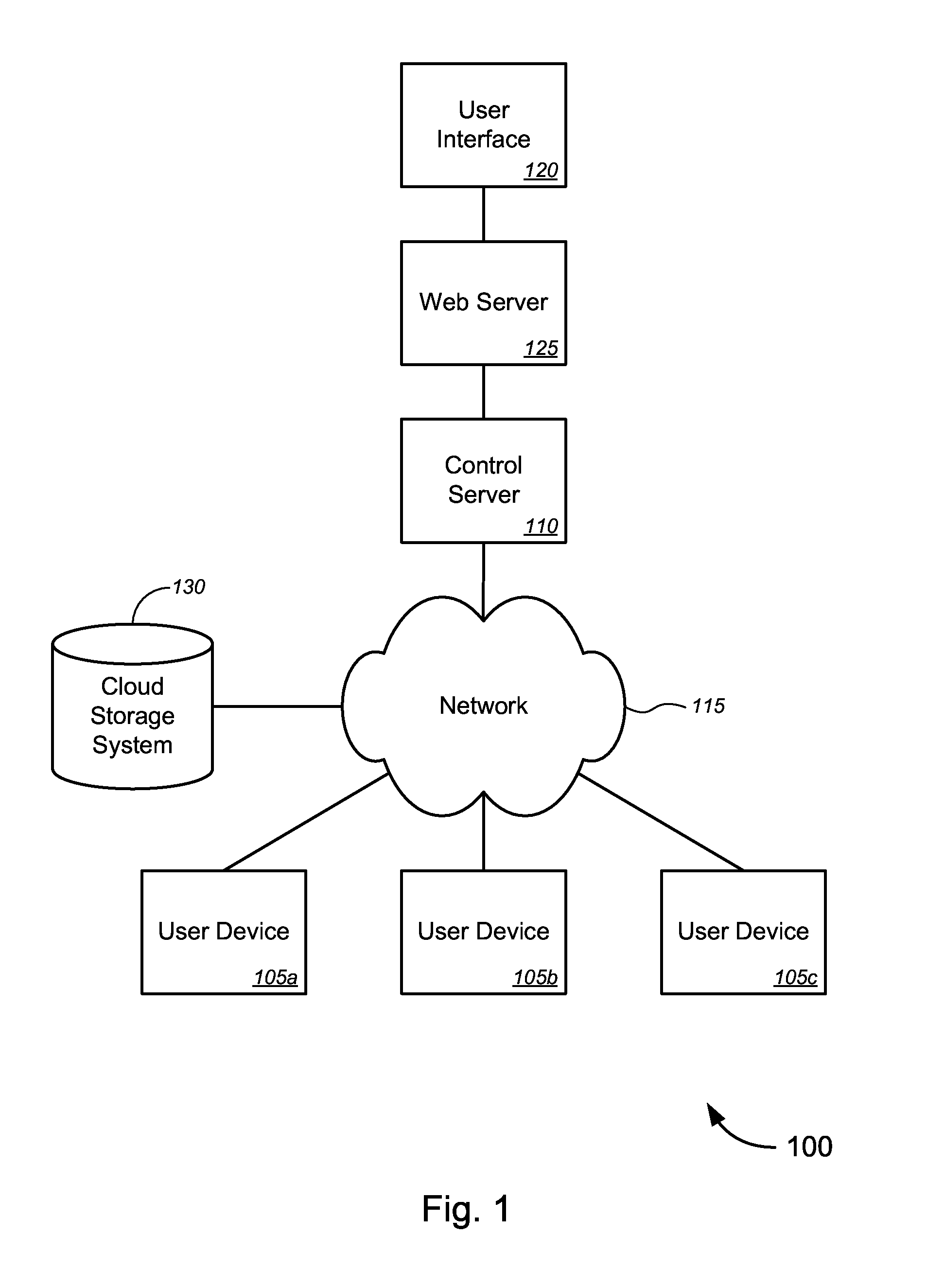
The patent text describes a way to use advanced user devices, like data processing, memory, and sensors, to create a distributed infrastructure for cloud computing, application hosting, and data storage. This means that these user devices can be connected to a network and used as a part of the infrastructure without needing additional networking equipment. The more user devices that are added to the network, the more capacity it expands, and the more processing power and storage capacity each device has, the larger the distributed infrastructure can become. This approach allows for a low-maintenance, cost-effective way to establish, operate, and maintain a reliable infrastructure for high-definition video calling, delivery, and gaming services, amongst others.

Problems solved by technology

These services require establishing, operating, and maintaining such facilities, as well as the networking infrastructure required to implement distributed computing or distributed data storage or the like, all of which may add to the cost of the resultant cloud services.
Further, hosting providers typically host applications for many different entities from a small number of locations, making the entire system susceptible to losses to a significant portion of the services in the case that one or more of the number of locations experience system crashes, perhaps due to events, including, without limitation, sudden high demand, natural or man-made disasters, local / regional power grid issues, and / or the like.
Finally, Content Delivery Networks, which replicate and cache data closer to the users, typically use a limited number of peering locations that cache content closer to users, which may result in data congestion—and thus long data transmission times.

Method used


Image

  • Distributed Infrastructure
  • Distributed Infrastructure
  • Distributed Infrastructure

Examples


Embodiment Construction

[0038]While various aspects and features of certain embodiments have been summarized above, the following detailed description illustrates a few exemplary embodiments in further detail to enable one of skill in the art to practice such embodiments. The described examples are provided for illustrative purposes and are not intended to limit the scope of the invention.

[0039]In the following description, for the purposes of explanation, numerous specific details are set forth in order to provide a thorough understanding of the described embodiments. It will be apparent to one skilled in the art, however, that other embodiments of the present invention may be practiced without some of these specific details. In other instances, certain structures and devices are shown in block diagram form. Several embodiments are described herein, and while various features are ascribed to different embodiments, it should be appreciated that the features described with respect to one embodiment may be i...


PUM


Abstract

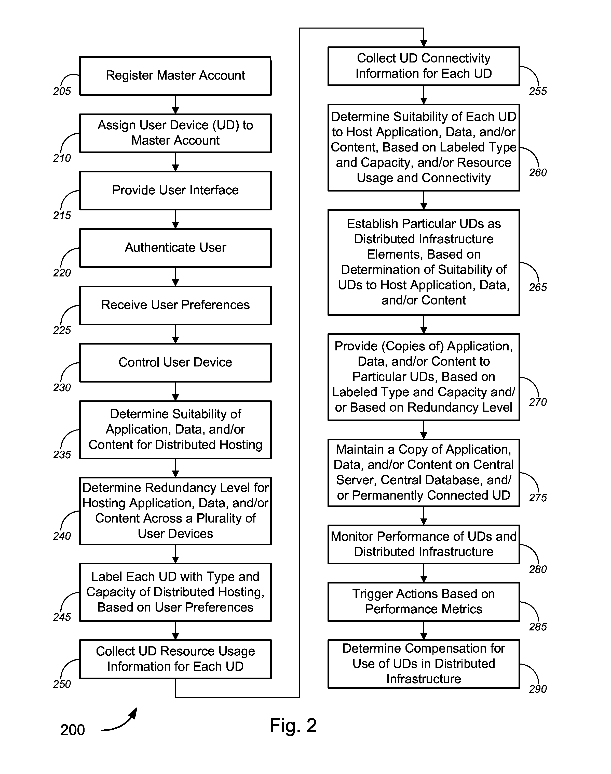
Novel tools and techniques for implementing distributed infrastructure are provided. In some techniques, a plurality of user devices, each at a customer premises, can provide video calling services over a network. In some embodiments, each of one or more user devices might be established as a distributed infrastructure element for cloud computing, cloud-based application hosting, and / or cloud-based data storage. One or more software applications, customer data, and / or media content (collectively, “hosted content”) might be provided to the one or more user devices for hosting thereon. Resource usage information and / or network connectivity information might be collected for each user device, and suitability of a user device to host the hosted content might be determined based at least in part on the collected resource usage information and / or network connectivity information. One or more courses of action may be determined, and invoked, based on performance metrics of the user devices.

Description

CROSS-REFERENCES TO RELATED APPLICATIONS[0001]This application claims the benefit, under 35 U.S.C. §119(e), of the following applications: provisional U.S. Patent Application No. 61 / 877,928, filed Sep. 13, 2013 by Ahmed et al. and titled “Mobile Presence Detection” (attorney docket no. 0414.12-PR, referred to herein as the “'928 Application”); provisional U.S. Patent Application No. 61 / 874,903, filed Sep. 6, 2013 by Shoemake et al. and titled “Virtual Window” (attorney docket no. 0414.11-PR, referred to herein as the “'903 Application”); provisional U.S. Patent Application No. 61 / 872,603, filed Aug. 30, 2013 by Shoemake et al. and titled “Physical Presence and Advertising” (attorney docket no. 0414.10-PR, referred to herein as the “'603 Application”); provisional U.S. Patent Application No. 61 / 858,518, filed Jul. 25, 2013 by Shoemake et al. and titled “Video Calling and Conferencing Advertising” (attorney docket no. 0414.08-PR, referred to herein as the “'518 Application”); provisio...

Claims


Application Information

Patent Timeline
IPC IPC(8): H04N21/2743
CPCH04N21/2743H04N21/42203H04N21/4223H04N21/44008H04N23/661G06F3/0484H04L67/10H04L67/02H04L43/04H04L43/08
Inventor AHMED, SYED NADEEMSHOEMAKE, MATTHEW B.
Owner BISCOTTI
Learn More