
Cryogenic tank assembly

a technology of cryogenic tanks and assembly parts, which is applied in the direction of transportation and packaging, fuel systems for specific fuels, container discharging methods, etc., can solve the problems of pump cavitate, pressure variation, and/or reducing the performance of the aircraft engin

Active Publication Date: 2014-06-26
GENERAL ELECTRIC CO
View PDF8 Cites 33 Cited by
  • Summary
  • Abstract
  • Description
  • Claims
  • Application Information

AI Technical Summary

Benefits of technology

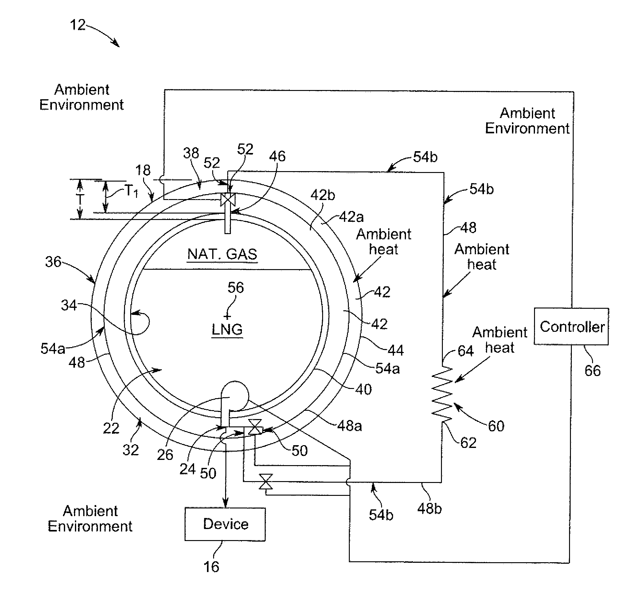
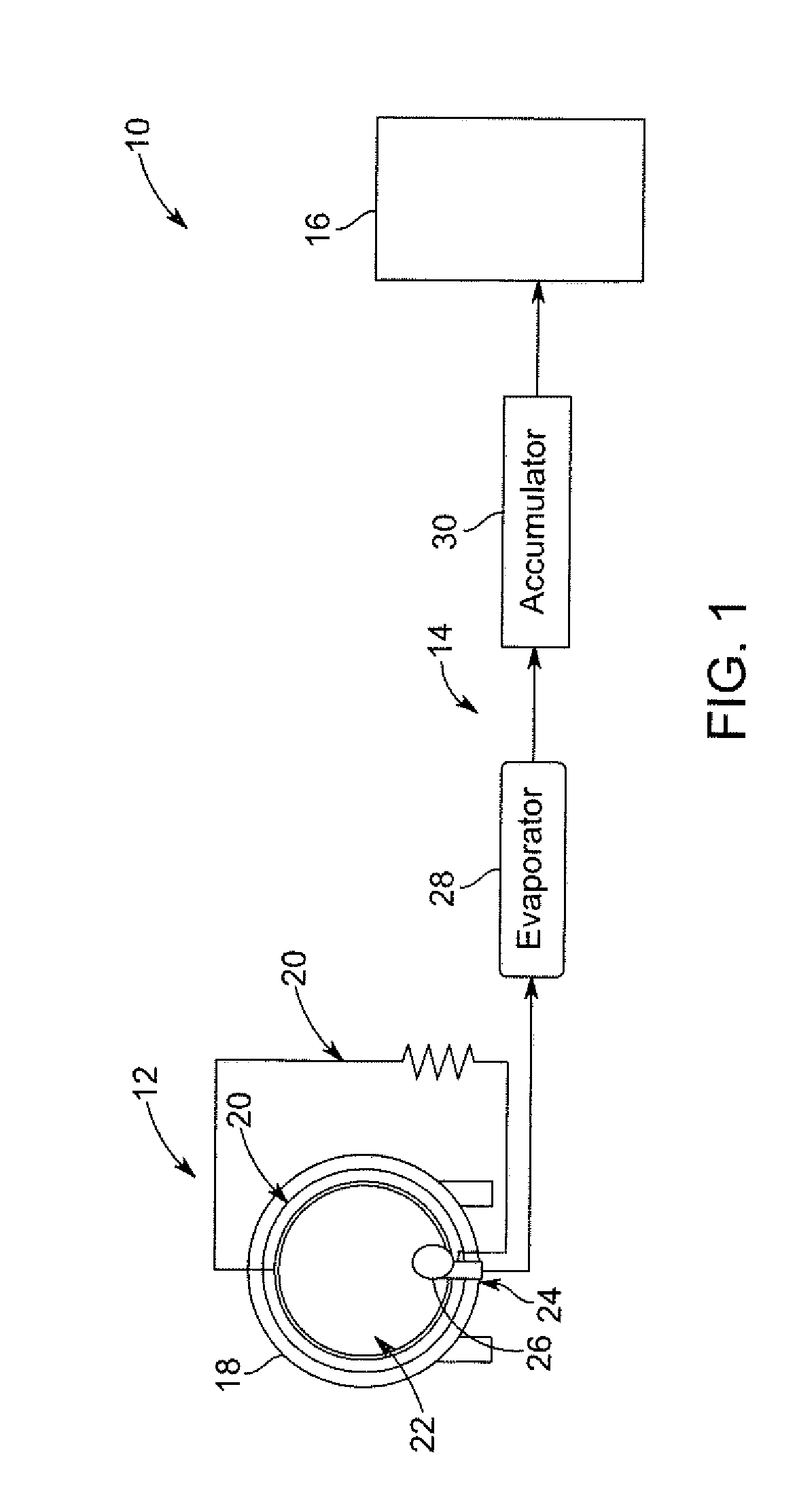
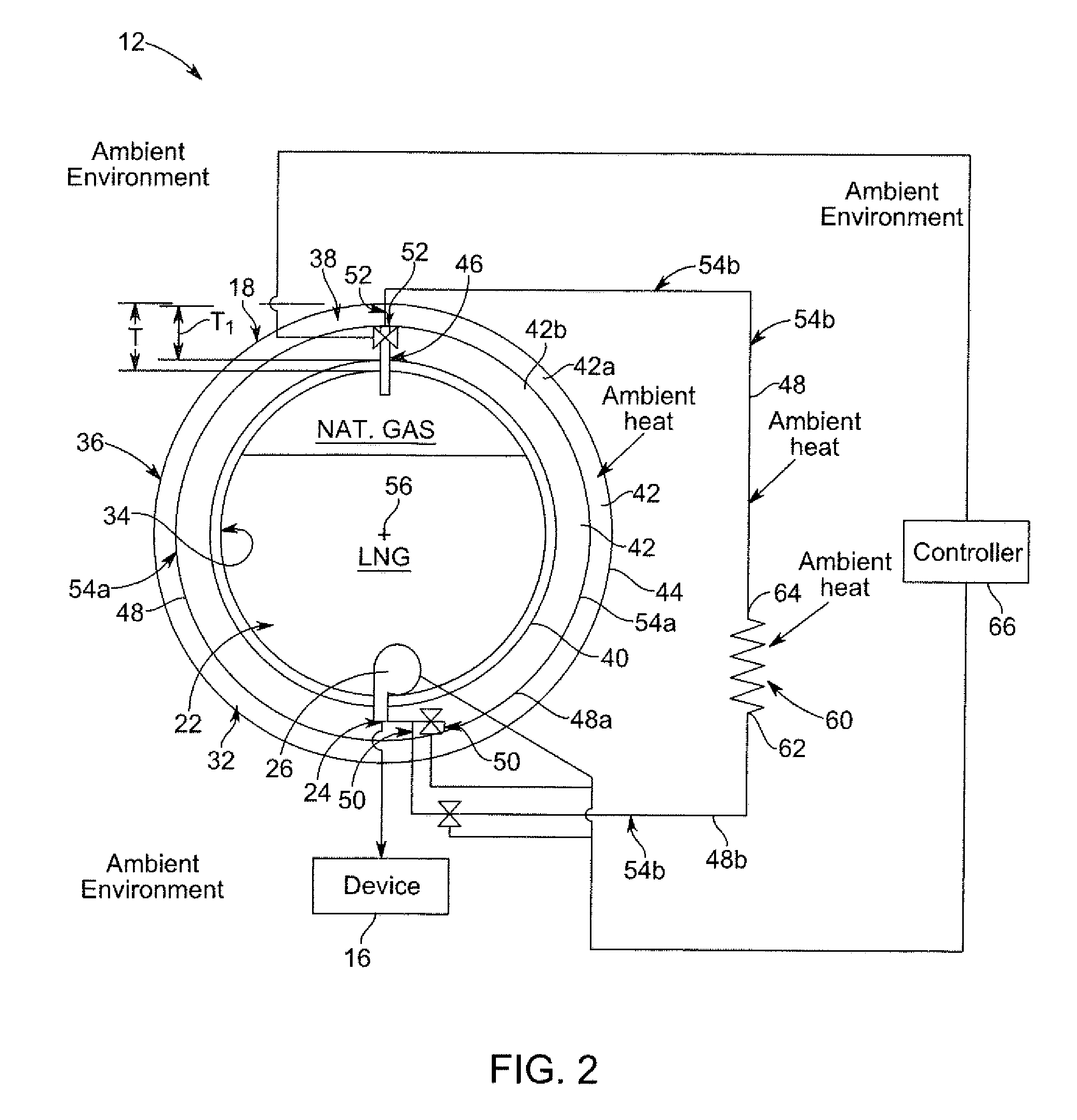
This patent describes a cryogenic tank assembly for storing and regulating pressure of liquefied natural gas (LNG) for use in aircraft. The assembly includes a cryogenic tank with an internal volume, a recirculation conduit, a pressure regulation system, and a source of LNG. The recirculation conduit connects the inlet and outlet of the cryogenic tank, and the pressure regulation system regulates the pressure within the internal volume of the cryogenic tank by receiving and transferring heat from the ambient environment to the LNG flow within the recirculation conduit, before injecting the natural gas flow into the internal volume through the inlet. The technical effect is the regulation of pressure within the cryogenic tank to ensure safe and efficient use of LNG in aircraft.

Problems solved by technology

Such a decrease in pressure within the internal volume of the cryogenic tank may cause pressure variations downstream of the pump during operation of the aircraft engine.
In other words, the pressure of natural gas supplied to the aircraft engine may vary over time, which may decrease the performance and / or disrupt operation of the aircraft engine.
Moreover, decreasing pressure within the internal volume of the cryogenic tank may cause the pump to cavitate.
In addition or alternative to decreasing the reliability and / or increasing the cost of operating the pump, pump cavitation may decrease performance and / or disrupt operation of the pump.

Method used


Image

  • Cryogenic tank assembly
  • Cryogenic tank assembly
  • Cryogenic tank assembly

Examples


Embodiment Construction

[0014]Various embodiments will be better understood when read in conjunction with the appended drawings. To the extent that the figures illustrate diagrams of the functional blocks of various embodiments, the functional blocks are not necessarily indicative of the division between hardware circuitry. Thus, for example, one or more of the functional blocks (e.g., processors, controllers, memories, and / or the like) may be implemented in a single piece of hardware (e.g., a general purpose signal processor, random access memory, hard disk, and / or the like) or multiple pieces of hardware. Similarly, any programs may be stand-alone programs, may be incorporated as subroutines in an operating system, may be functions in an installed software package, and / or the like. It should be understood that the various embodiments are not limited to the arrangements and instrumentality shown in the drawings.

[0015]As used herein, the term “system” may include a hardware and / or software system that oper...


PUM


Abstract

A cryogenic tank assembly includes a cryogenic tank having an internal volume that is configured to contain liquefied natural gas (LNG). The cryogenic tank includes an inlet and an outlet that are each fluidly connected to the internal volume. The assembly includes a recirculation conduit coupled in fluid communication between the inlet and the outlet. The recirculation conduit extends along a path between the inlet and outlet external to the internal volume of the cryogenic tank such that the path is configured to be exposed to an ambient environment of the cryogenic tank. The recirculation conduit is configured to: receive a flow of LNG from the internal volume through the outlet; transfer heat from the ambient environment to the LNG flow to change the LNG flow to a flow of natural gas; and inject the natural gas flow into the internal volume of the cryogenic tank through the inlet.

Description

BACKGROUND[0001]It has been demonstrated that cryogenic fluids may be used on-board aircraft as a fuel source. For example, some aircraft engines, such as the Tu-155 made by Tupolev, were configured to use natural gas as fuel. The natural gas may be stored on-board the aircraft as liquid natural gas (LNG), which is a cryogenic fluid. LNG can be stored on-board aircraft within a cryogenic tank that holds a volume of the LNG. A pump typically dispenses LNG from the internal volume of the cryogenic tank and supplies the LNG to the aircraft engine as natural gas via piping. But, as the level of LNG within the internal volume of the cryogenic tank decreases, the surface pressure exerted on the surface of the LNG may decrease. Such a decrease in pressure within the internal volume of the cryogenic tank may cause pressure variations downstream of the pump during operation of the aircraft engine. In other words, the pressure of natural gas supplied to the aircraft engine may vary over time,...

Claims


Application Information

Patent Timeline
Patent Type & Authority Applications(United States)
IPC IPC(8): F17C7/04
CPCF17C7/04B64D37/30F17C2201/0104F17C2201/0128F17C2201/054F17C2203/03F17C2203/032F17C2203/0325F17C2203/0604F17C2203/0626F17C2203/0629F17C2205/0119F17C2205/0326F17C2205/0329F17C2205/0332F17C2205/0338F17C2205/035F17C2205/0397F17C2221/033F17C2223/0161F17C2223/0169F17C2223/033F17C2225/0123F17C2227/0107F17C2227/0135F17C2227/0178F17C2227/0185F17C2227/0302F17C2227/0381F17C2227/039F17C2227/0397F17C2250/01F17C2250/032F17C2265/066F17C2270/0189F17C2270/07
Inventor TANG, CHING-JENHUDY, LAURA MICHELE
Owner GENERAL ELECTRIC CO
Learn More