
Compact motor

a compact motor and cylinder technology, applied in the direction of mechanical energy handling, dynamo-electric machines, supports/enclosements/casings, etc., can solve the problem of difficult stabilization of the bend in the fpc, and achieve the effect of avoiding peeling and cracking of the wiring pattern well

Inactive Publication Date: 2014-06-26
COPAL CO LTD
View PDF19 Cites 0 Cited by
  • Summary
  • Abstract
  • Description
  • Claims
  • Application Information

AI Technical Summary

Benefits of technology

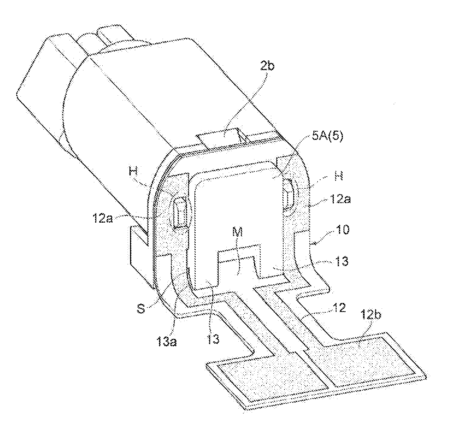
The present invention provides a compact motor that prevents peeling and cracking of the wiring pattern on a flexible printed circuit board when it is bent. The motor has aprojecting part that regulates the bending position of the circuit board, ensuring stable bending at a preset position. This prevents solder peeling, peeling from the wiring pattern material, or cracking of the winding pattern. The motor avoids direct damage to the winding pattern and improves the alignment of connection terminals and the wiring pattern during soldering work. Overall, the invention prevents issues that might occur during bending of flexible printed circuit boards.

Problems solved by technology

However, with the prior art compact motor described previously, the FPC is simply bent along the outer surface of the cylindrical housing, so there is the problem that the smaller the bending angle, the more likely it is that the FPC wiring pattern will peel away from the substrate at the bent part and that cracks will occur in the wiring pattern causing disconnects, and the more difficult it will be to stabilize the bend in the FPC.

Method used


Image

  • Compact motor
  • Compact motor
  • Compact motor

Examples


Embodiment Construction

[0031]Following, we will give a detailed description of a preferred embodiment of the compact motor of the present invention while referring to drawings. We will describe this using the extending direction of the rotation axis line L as “front-back,” and the direction orthogonal to the rotation axis line L as “up-down.” Also, the same or equivalent constitutional parts will be given the same code numbers, and redundant explanation will be omitted.

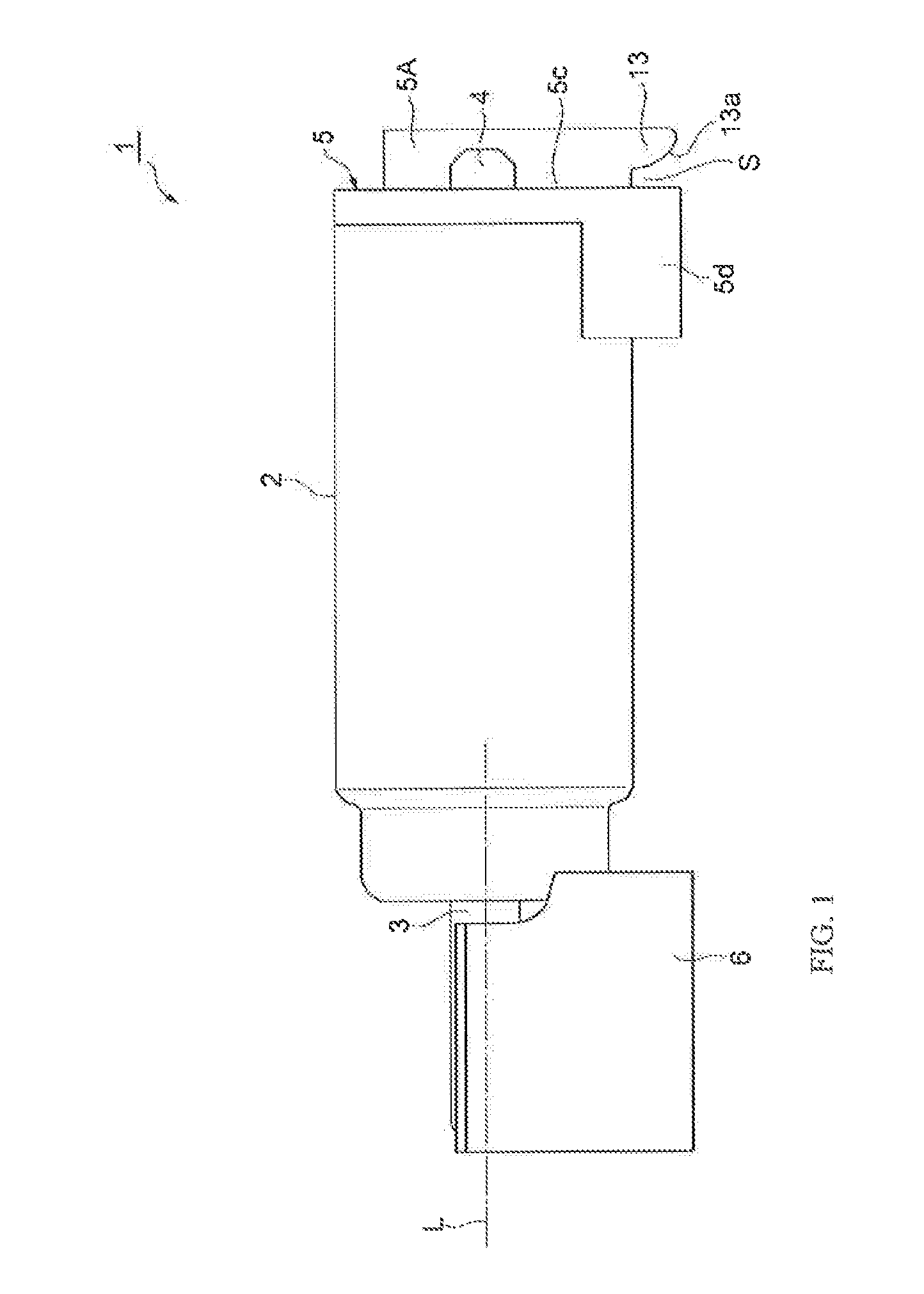
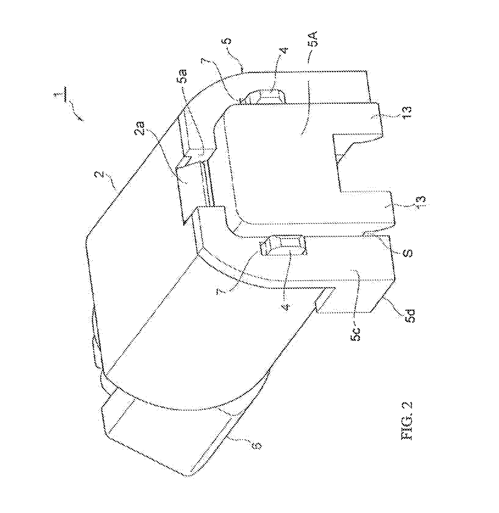
[0032]As shown in FIG. 1 to FIG. 3, the vibration motor 1 consists of a cylinder type cored motor, and also, has a cylinder shaped metal housing 2 with diameter approximately 4 mm and length approximately 10 mm to promote compactness. A stator consisting of a permanent magnet having N and S poles is fixed to the inner wall surface of the housing 2, and a rotor on which a coil is wound on an iron core is housed inside the housing 2. At the center of this rotor is fixed a rotation shaft 3 which is supported by a bearing inside the housing 2, ...


PUM


Abstract

A compact motor which avoids peeling and cracking of the circuit board wiring pattern upon bending the printed circuit board. A projecting part (13), projecting toward the bottom side of the bracket (5), is provided on the back surface (5c) of the bracket (5) of a compact motor. A board insertion groove (S) is formed between the projecting part (13) and the back surface (5c). The flexible printed circuit board (10), inserted inside the board insertion groove (S), abuts the projecting part (13) and is bent facing the back. When the printed circuit board (10) is inserted into the board insertion groove (S) and bent, the printed circuit board (10) is in a state abutting the curved part (13a) of the projecting part (13), so the curved part (13a) of the projecting part (13) regulates bending and, by doing this, stabilizes bending of the flexible printed circuit board (10).

Description

[0001]This application claims priority from Japanese patent application serial no. 2012-283381 filed Dec. 26, 2012.FIELD OF THE INVENTION[0002]The present invention relates to a cylinder type compact motor.BACKGROUND OF THE INVENTION[0003]In the past, as technology for this kind of field, there is Unexamined Patent Publication No. 2002-96025. The compact motor noted in this publication has an end bracket provided at the back end of a cylinder shaped housing. Connection terminals are exposed from this end bracket, and a wiring pattern of a flexible printed circuit board (hereafter referred to as FPC) is electrically connected by solder. The FPC has a vertically long rectangular shape, this FPC is bent facing the inside along the outer surface of the cylindrical housing, and by doing this, the FPC extends in parallel to the housing. Then, the motor in this state is mounted inside a mobile electronic device, and electrical contact is made between the mobile electronic device external s...

Claims


Application Information

Patent Timeline
IPC IPC(8): H02K11/00
CPCH02K11/0094H02K5/225H02K2211/03H02K5/22H02K5/04H02K5/24H02K7/061H02K7/1876H02K7/1892H02K11/30H02K11/33
Inventor KATADA, YOSHINORI
Owner COPAL CO LTD
Learn More