
Active stylus for touch sensing applications

a technology of touch sensing and active stylus, which is applied in the direction of instruments, electric digital data processing, input/output processes of data processing, etc., can solve the problems of large tip of the stylus pen, inconvenient handling, and large portion of the touch sensing signal that carries touch information

Active Publication Date: 2014-06-26
LOGITECH EURO SA
View PDF3 Cites 155 Cited by
  • Summary
  • Abstract
  • Description
  • Claims
  • Application Information

AI Technical Summary

Benefits of technology

The present invention relates to a control device that can be used with a touch-screen containing device, such as a smartphone or tablet, regardless of the manufacturer or specific detection techniques of the device. The control device includes a conductive tip, a peak signal detector, a phase discriminator, an amplifier, a controlling capacitor, a switching device, a controller, and a power amplifier. The control device can detect the capacitive sensing signals generated by the conductive tip and provide input to the touch-screen containing device. The invention provides a universal solution for interacting with touch-screen devices, regardless of the manufacturer or specific detection techniques.

Problems solved by technology

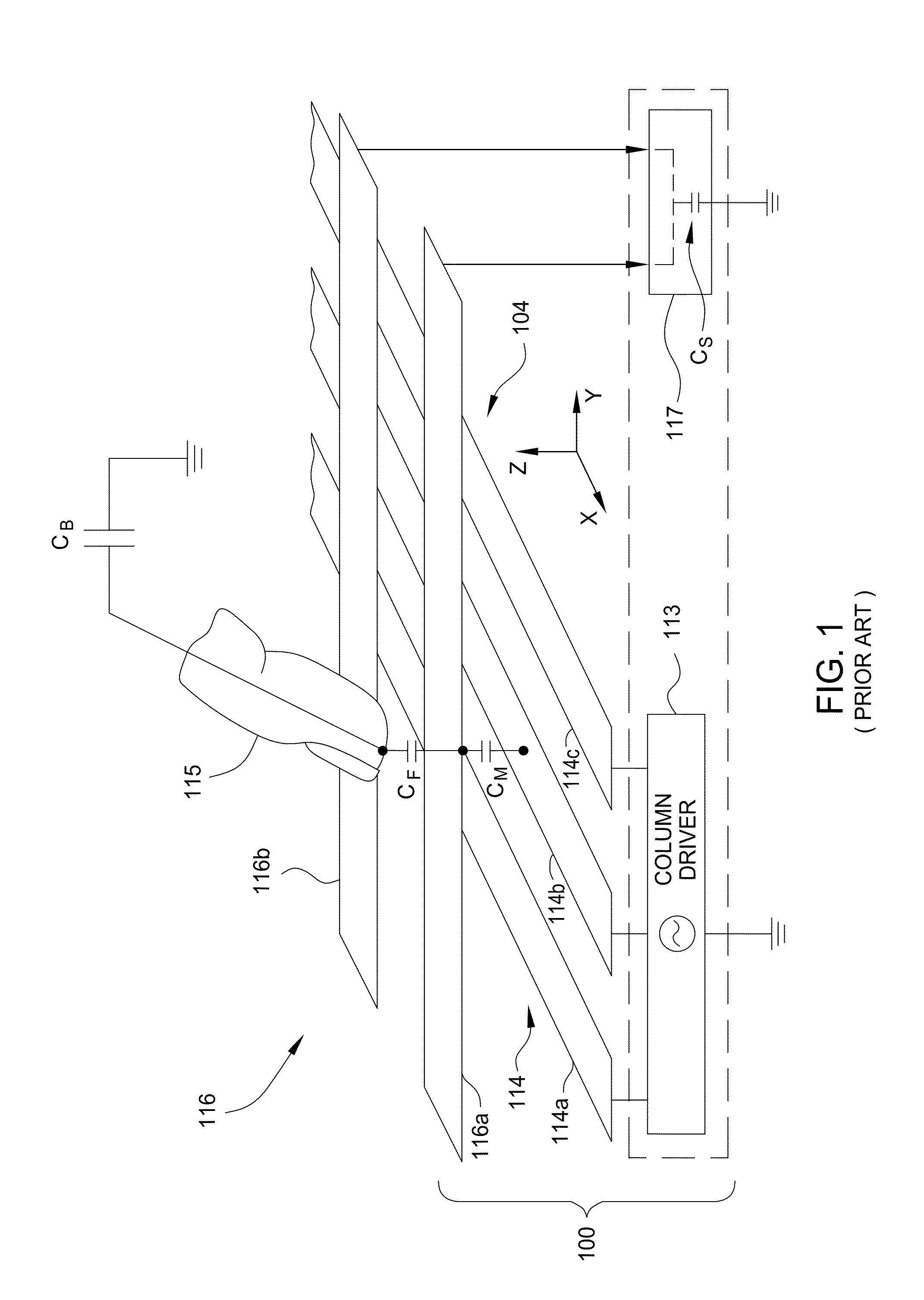
Physically tethered stylus pens require some electrical and physical integration with touch-screen tablet computer, and are often inconvenient to handle and can easily fail due to wear on the connecting components that tether the stylus pen to the touch-screen tablet computer.
These other sources, or error sources, can cause a change in the operation of touch sensing that causes the portion of the touch sensing signal that carries touch information to inaccurately reflect the amount or position of the touch.
Thus, the tip of the stylus pen is large enough to interfere with the electric field lines created between the drive and sense electrodes of the touch screen device.
As such, conventional styluses are passive input devices in that they are incapable of actively altering the input received by the capacitive sensing components in the touch screen or sensing a touch-induced capacitance change in a capacitive touch sensor panel when it is desired to input touch related information.

Method used


Image

  • Active stylus for touch sensing applications
  • Active stylus for touch sensing applications
  • Active stylus for touch sensing applications

Examples


Embodiment Construction

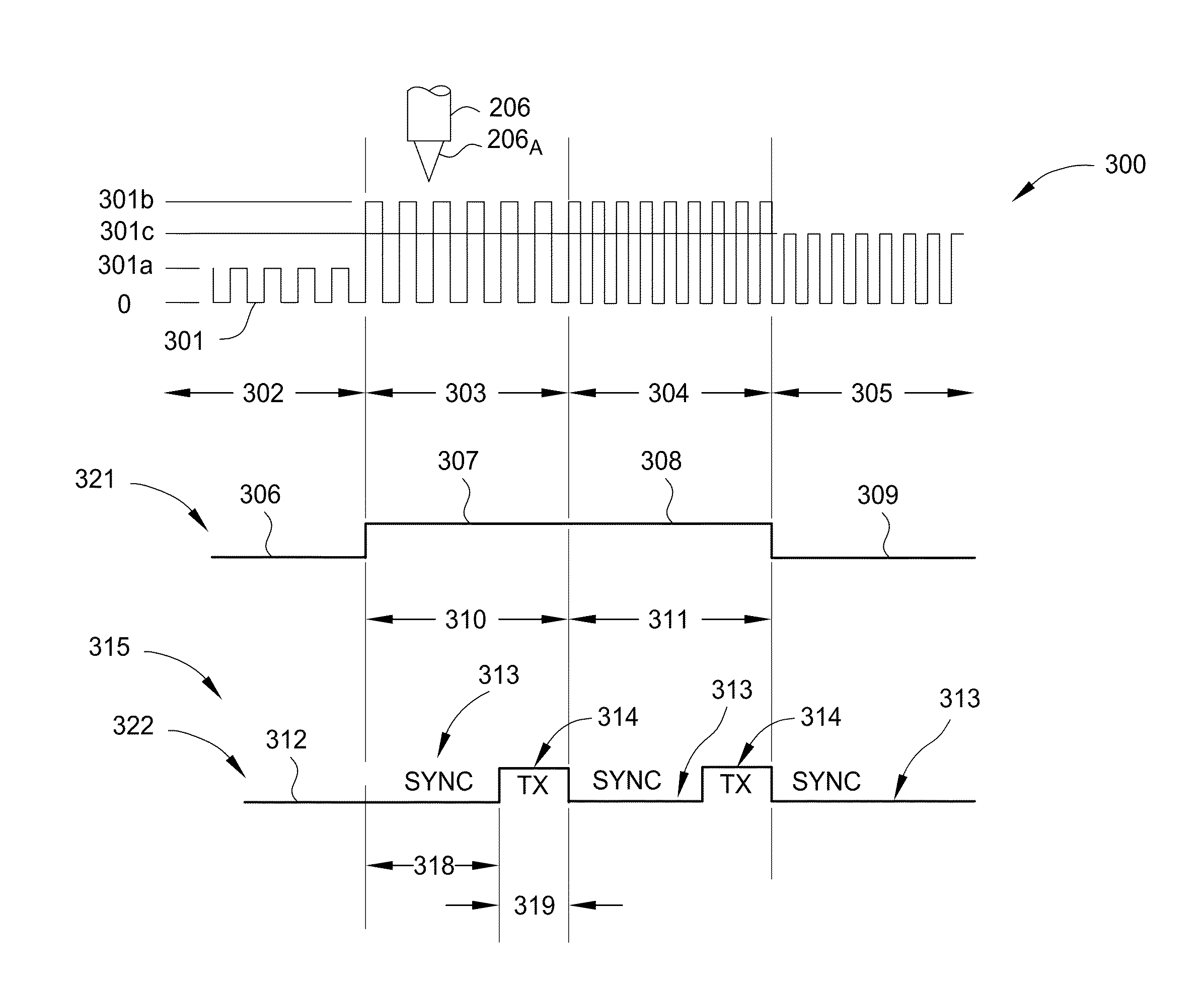
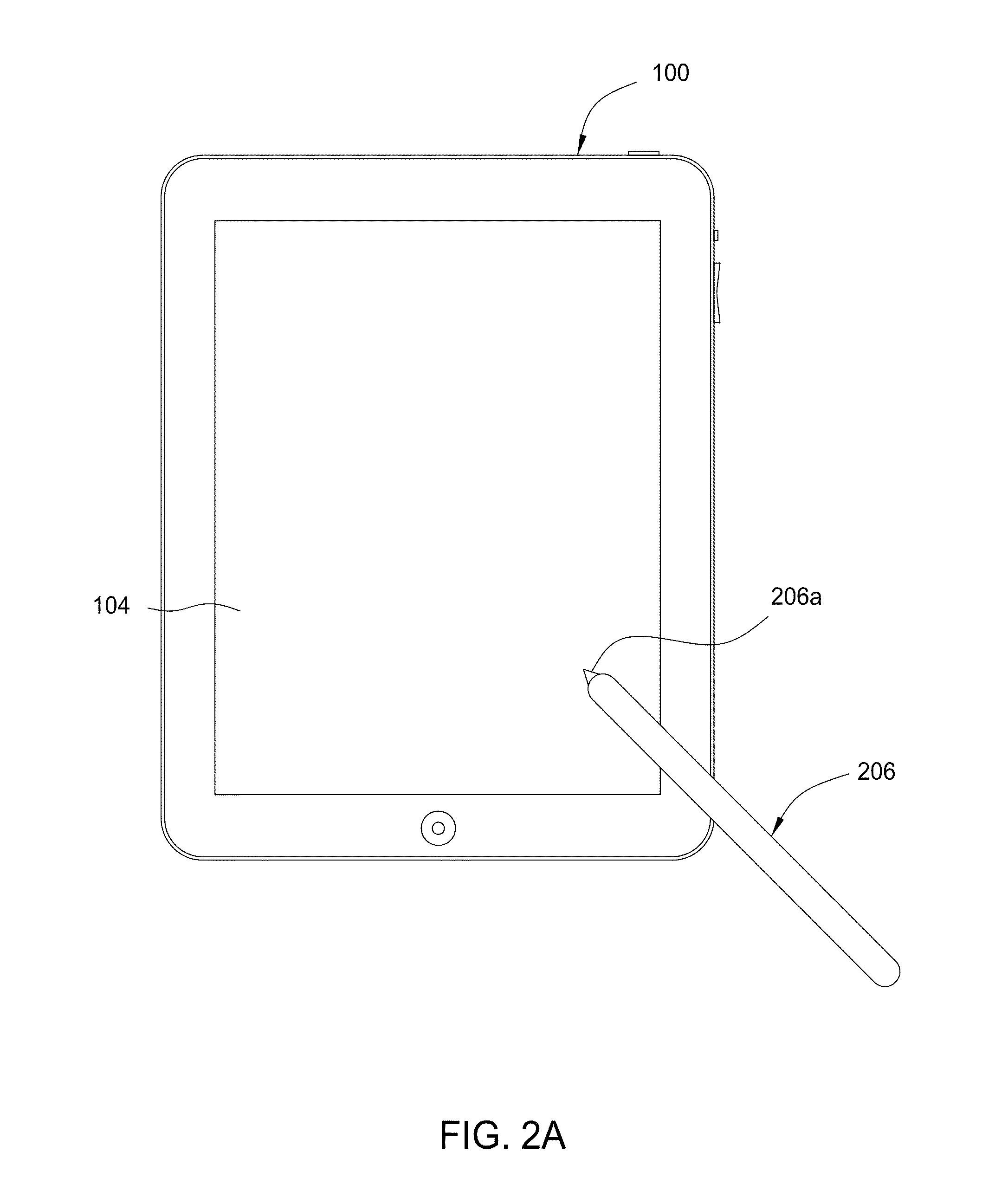
[0045]Embodiments of the invention generally relate to methods and apparatuses that are used to actively control the interaction of a handheld device with a touch-screen containing device, such as a touch-screen tablet computer. Embodiments of the invention provide a universal handheld device that is able to provide input to any type of capacitive sensing touch-screen containing device, regardless of the manufacturer or, in some embodiments, knowledge of the touch-screen containing device manufacturer's specific capacitive touch-sensing detection techniques. In general, the handheld device disclosed herein is an electronic stylus pen, or also referred to herein as simply a “stylus pen,” that a user uses to provide input to control some aspect of the touch sensitive device. In some configurations, the “stylus pen” includes an “active stylus pen” that is configured to actively alter the capacitive sensing signal generated by the touch sensing components in the touch-screen containing ...


PUM


Abstract

Embodiments relate generally to control devices, such as human interface devices, configured for use with a touch-screen containing device. More specifically, the present invention relates to methods and various apparatus that are used to actively control the interaction of a handheld device, such as a stylus pen, with a touch-screen containing device. Embodiments of the invention provide a universal handheld device that is able to provide input to any type of capacitive sensing touch-screen containing device, regardless of the manufacturer or, in some embodiments, without knowledge of the touch-screen containing device manufacturer's specific capacitive touch-sensing detection techniques.

Description

CROSS-REFERENCE TO RELATED APPLICATIONS[0001]This application claims benefit of U.S. Provisional Patent Application Ser. No. 61 / 738,797, filed Dec. 18, 2012 entitled “Electronically Augmented Pen Tip For A Touch Pad Digitizer” (Atty Dkt No. LOGI 0003L), U.S. Provisional Patent Application Ser. No. 61 / 762,222, filed Feb. 7, 2013, entitled “Electronically Augmented Pen Tip For A Touch Pad Digitizer” (Atty. Dkt. No. LOGI 0003L02) and U.S. Provisional Patent Application Ser. No. 61 / 790,310, filed Mar. 15, 2013, entitled “Active Stylus For Touch Sensing Applications” (Atty. Dkt. No. LOGI 0003L03), and U.S. Provisional Patent Application Ser. No. 61 / 791,577, filed Mar. 15, 2013, entitled “Method and System for Discriminating Stylus and Touch Interactions” (Atty. Dkt. No. LOGI 0005USL), which are all herein incorporated by reference.BACKGROUND OF THE INVENTION[0002]1. Field of the Invention[0003]The present invention relates to an apparatus and methods for actively controlling the interact...

Claims


Application Information

Patent Timeline
IPC IPC(8): G06F3/044G06F3/0354
CPCG06F3/044G06F3/03545G06F3/0441G06F3/0442G06F3/0446
Inventor VLASOV, MAXIM
Owner LOGITECH EURO SA
Learn More