
Color balance in digital photography

Active Publication Date: 2014-06-26
DUELIGHT
View PDF4 Cites 59 Cited by
  • Summary
  • Abstract
  • Description
  • Claims
  • Application Information

AI Technical Summary

Benefits of technology

The present invention allows for the generation of a digital photograph that has consistent white balance in a scene that includes regions that are primarily illuminated by a strobe of one color balance and other regions that are primarily illuminated by ambient illumination of a different color balance.

Problems solved by technology

However, a digital photograph of the same white object will appear orange without compensation for the orange white balance imparted by the incandescent lamps.
In certain common scenarios, ambient lighting within a scene is not sufficient to produce a properly exposed digital photograph of the scene or certain subject matter within the scene.
However, the color of the strobe frequently does not match that of ambient illumination, creating a discordant appearance between objects illuminated primarily by the strobe and other objects illuminated primarily by ambient lighting.
Alternatively, a set of gain values that provides proper white balance for the LED will result in an overly orange appearance for objects primarily illuminated by ambient incandescent light.
Flooding does not correct for discordantly colored ambient light sources such as incandescent lamps or candles visible within the scene.
However, such a solution is impractical in many settings.
For example, a high-powered strobe is not conventionally available in small consumer digital cameras or mobile devices that include a digital camera subsystem.
Conventional consumer digital cameras have very limited strobe capacity and are incapable of flooding most scenes.
Furthermore, flooding a given environment, such as a public restaurant or indoor space, with an intense pulse of strobe illumination may be overly disruptive and socially unacceptable in many common settings.
As such, even when a high-powered strobe unit is available, flooding an entire scene may be disallowed.
More commonly, a combination of partial strobe illumination and partial ambient illumination is available, leading to discordant white balance within a resulting digital photograph.

Method used


Image

  • Color balance in digital photography
  • Color balance in digital photography
  • Color balance in digital photography

Examples


first embodiment

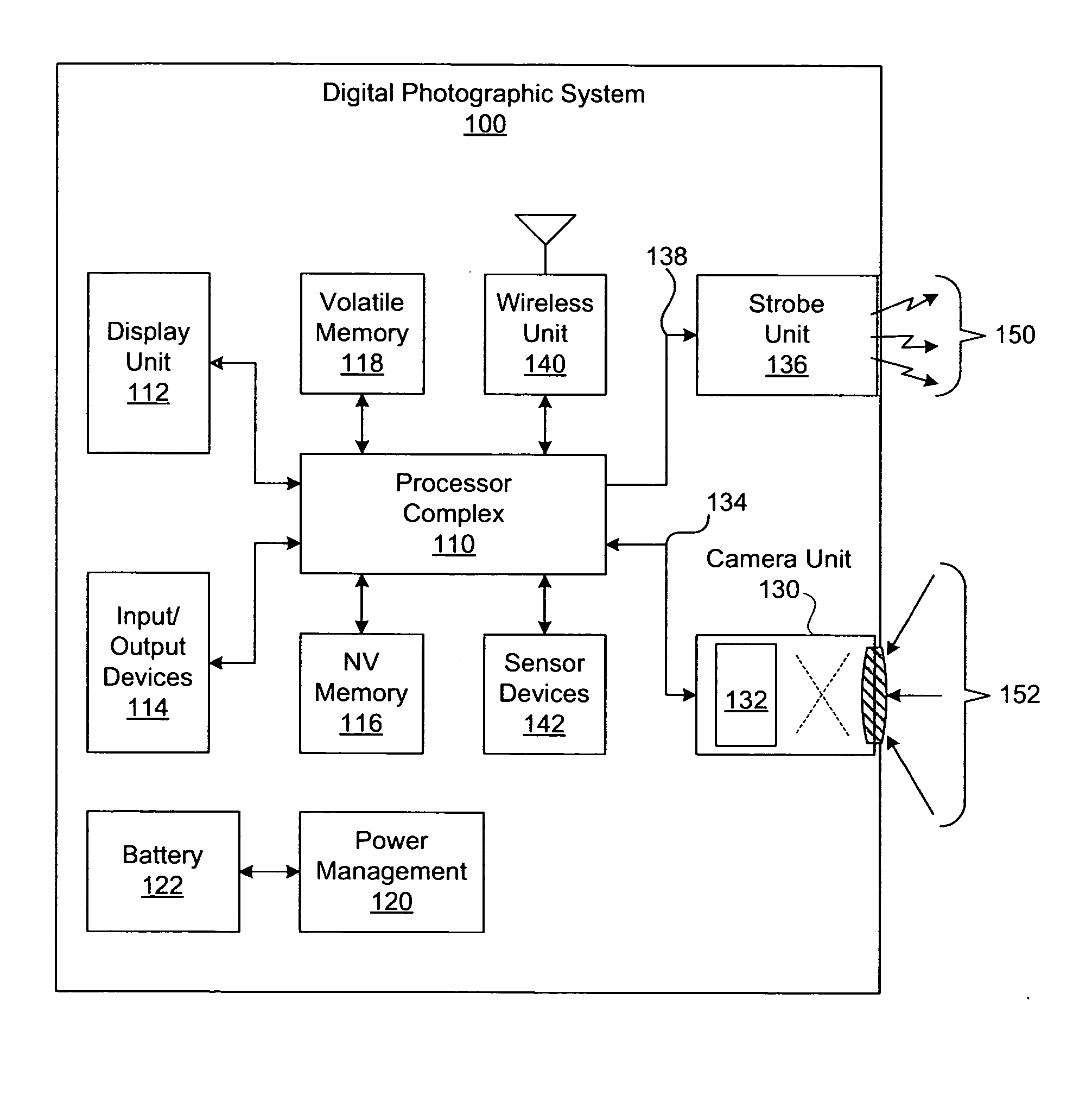
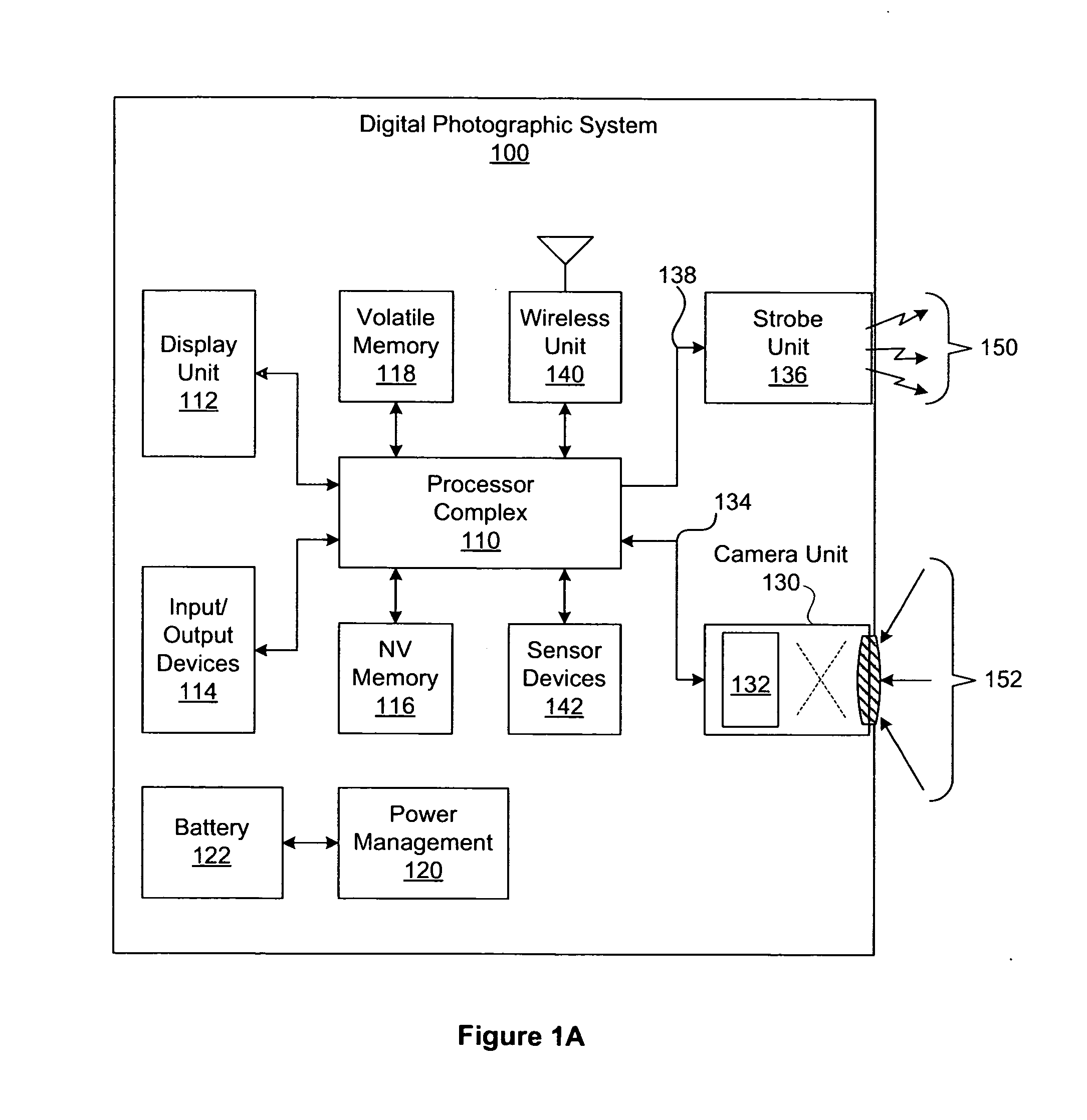
[0153]FIG. 7A is a flow diagram of method 700 for blending a strobe image with an ambient image to generate a blended image, according to the present invention. Although the method steps are described in conjunction with the systems of FIGS. 1A-1D, persons skilled in the art will understand that any system configured to perform the method steps, in any order, is within the scope of the present invention. In one embodiment, method 700 implements data flow 200 of FIG. 2A. The strobe image and the ambient image each comprise at least one pixel and may each comprise an equal number of pixels.

[0154]The method begins in step 710, where a processor complex within a digital photographic system, such as processor complex 110 within digital photographic system 100 of FIG. 1A, receives a strobe image and an ambient image, such as strobe image 210 and ambient image 220, respectively. In step 712, the processor complex generates a blended image, such as blended image 280, by executing a blend op...

second embodiment

[0155]FIG. 7B is a flow diagram of method 702 for blending a strobe image with an ambient image to generate a blended image, according to the present invention. Although the method steps are described in conjunction with the systems of FIGS. 1A-1D, persons skilled in the art will understand that any system configured to perform the method steps, in any order, is within the scope of the present invention. In one embodiment, method 702 implements data flow 202 of FIG. 2B. The strobe image and the ambient image each comprise at least one pixel and may each comprise an equal number of pixels.

[0156]The method begins in step 720, where a processor complex within a digital photographic system, such as processor complex 110 within digital photographic system 100 of FIG. 1A, receives a strobe image and an ambient image, such as strobe image 210 and ambient image 220, respectively. In step 722, the processor complex generates a color corrected strobe image, such as corrected strobe image data...

third embodiment

[0157]FIG. 8A is a flow diagram of method 800 for blending a strobe image with an ambient image to generate a blended image, according to the present invention. Although the method steps are described in conjunction with the systems of FIGS. 1A-1D, persons skilled in the art will understand that any system configured to perform the method steps, in any order, is within the scope of the present invention. In one embodiment, method 800 implements data flow 204 of FIG. 2C. The strobe image and the ambient image each comprise at least one pixel and may each comprise an equal number of pixels.

[0158]The method begins in step 810, where a processor complex within a digital photographic system, such as processor complex 110 within digital photographic system 100 of FIG. 1A, receives a strobe image and an ambient image, such as strobe image 210 and ambient image 220, respectively. In step 812, the processor complex estimates a motion transform between the strobe image and the ambient image. ...


PUM


Abstract

A technique for generating a digital photograph comprises blending two related images, each sampled according to a different illumination environment. The two related images are blended according to a blend surface function that includes a height discontinuity separating two different blend weight regions. Color consistency between the two related images is achieved by spatial color correction prior to blending. The technique enables a digital camera to generate a strobe image having an appearance of consistent color despite discordant strobe and ambient scene illumination.

Description

BACKGROUND OF THE INVENTION[0001]1. Field of the Invention[0002]Embodiments of the present invention relate generally to photographic systems, and more specifically to systems and methods for improved color balance in digital photography.[0003]2. Description of the Related Art[0004]A typical digital camera generates a digital photograph by focusing an optical image of a scene onto an image sensor, which samples the optical image to generate an electronic representation of the scene. The electronic representation is then processed and stored as the digital photograph. The image sensor is configured to generate a two-dimensional array of color pixel values from the optical image, typically including an independent intensity value for standard red, green, and blue wavelengths. The digital photograph is commonly viewed by a human, who reasonably expects the digital photograph to represent the scene as if observed directly. To generate digital photographs having a natural appearance, dig...

Claims


Application Information

Patent Timeline
IPC IPC(8): H04N9/73
CPCH04N9/735H04N5/2354G06T7/90H04N23/56H04N23/74H04N23/88G06T2207/20221
Inventor RIVARD, WILLIAM GUIEFEDER, ADAM BARRYKINDLE, BRIAN
Owner DUELIGHT
Learn More