

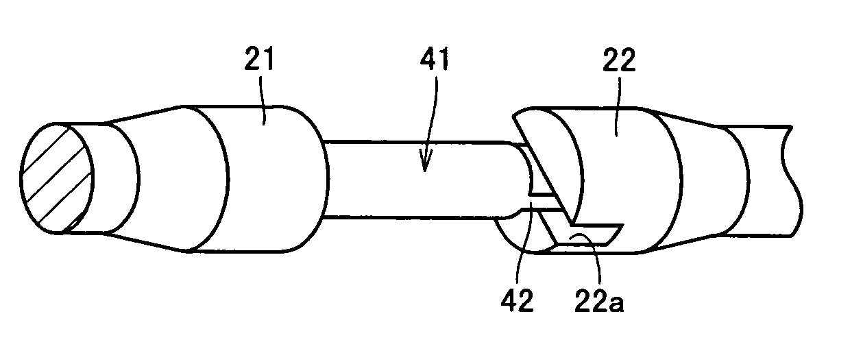
Rolling-contact shaft with joint claw
a technology of rolling contact shaft and joint claw, which is applied in the direction of mechanical equipment, rotary machine parts, solid-state diffusion coating, etc., can solve the problems of deformation, deformation, and difficulty in achieving an improvement in the fatigue life of both rolling contact shafts at the raceway of rolling-contact shafts, so as to achieve the improvement of both rolling contact fatigue li
- Summary
- Abstract
- Description
- Claims
- Application Information
AI Technical Summary
Benefits of technology
Problems solved by technology
Method used
Image


Examples
example 1
[0087] Example 1 of the present invention will be described hereinafter. Using SUJ2 material of the JIS as the raw material (1.0 mass % of C, 0.25 mass % of Si, 0.4 mass % of Mn, 1.5 mass % of Cr), tests to investigate the influence of the heat treatment history in the heat treatment step on various properties of a rolling-contact shaft with a joint claw were conducted. The investigated properties were: (1) hydrogen content, (2) austenite grain size, (3) Charpy impact value, (4) fracture stress value, and (5) rolling contact fatigue life.
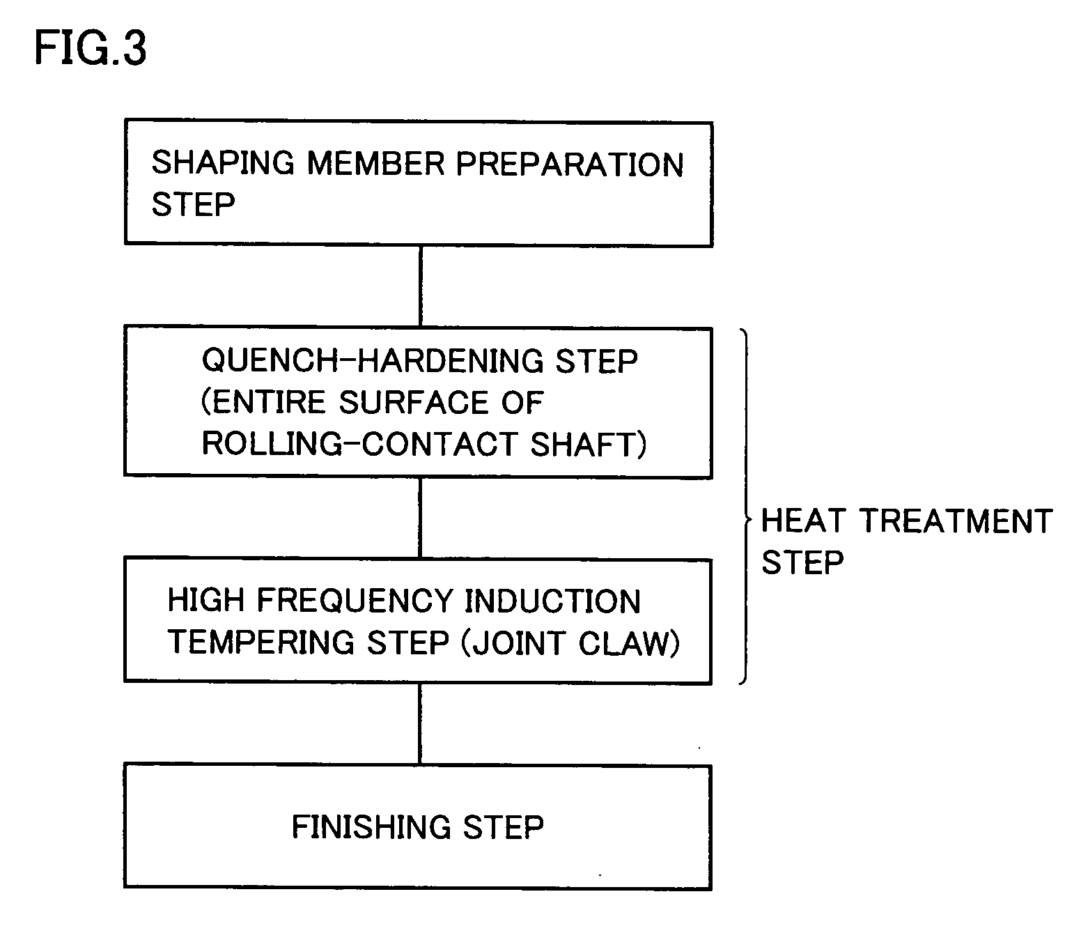
[0088] Eight specimens labeled as Specimens A-H were employed for the test. The heat treatment history of each specimen is as set forth below. Specimens A-D (examples of present invention) were carbonitrided by being retained for 150 minutes at the temperature of 850° C. in a mixture gas atmosphere of RX gas and ammonia (NH3) gas. The heat treatment pattern employed was similar to the heat treatment step of FIG. 5, provided that high frequency indu...
example 2
[0120] Example 2 of the present invention will be described hereinafter. Using SUJ2 material of the JIS as the raw material (1.0 mass % of C, 0.25 mass % of Si, 0.4 mass % of Mn, 1.5 mass % of Cr), tests to investigate the influence of the heat treatment history in the heat treatment step on various properties of a rolling-contact shaft with a joint claw were conducted. The investigated properties were: (1) rolling contact fatigue life, (2) Charpy impact value, (3) static fracture toughness value, (4) fracture stress value, (5) secular dimensional distortion rate, and (6) rolling contact fatigue life under contaminated lubricant environment.
[0121] Three specimens labeled as Member X, Member Y and Member Z were employed as the specimens for the test. The heat treatment history of each specimen is as set forth below. For Member X (comparative example: general quenching), carbonitriding was not carried out, and quenching was effected. Secondary quenching was not carried out. For Membe...
example 3
[0145] Example 3 of the present invention will be described hereinafter. Using SUJ2, SCM 420 and S53C of the JIS as the raw materials, rolling-contact shafts with joint claws at one end were produced. Tests to investigate the influence of the heat treatment history in the heat treatment step on various properties of a rolling-contact shaft with a joint claw were conducted. The investigated properties were: (1) austenite grain size, (2) hydrogen content at joint claw, (3) amount of retained austenite at raceway, (4) nitrogen content at raceway, (5) surface hardness at joint claw, and (6) torsional strength of joint claw.
[0146] Five specimens labeled as Examples A and B (rolling-contact shaft with joint claw of present invention) and Comparative Examples C, D and E (conventional rolling-contact shaft with joint claw) were employed for the test. The heat treatment history of each specimen is as set forth below.
[0147] Examples A and B were subjected to a heat treatment according to a ...
PUM
| Property | Measurement | Unit |
|---|---|---|
| Fraction | aaaaa | aaaaa |
| Percent by mass | aaaaa | aaaaa |
| Percent by mass | aaaaa | aaaaa |
Abstract
Description
Claims
Application Information