Touch panel

Inactive Publication Date: 2014-06-26
LG INNOTEK CO LTD
View PDF9 Cites 2 Cited by
  • Summary
  • Abstract
  • Description
  • Claims
  • Application Information

AI Technical Summary

Benefits of technology

[0015]Accordingly, the pattern is formed such that the current value of the sensing electrode can be increased at a region where the wire electrode is lengthened, thereby compensating for the influence of the wire resistance.
[

Problems solved by technology

Since a use region of a user is limited at the front surface of the touch panel due to the bezels formed at left and right sides of the touch panel, the user may feel inconvenience when using the touch panel.
That is, when the wire electrode is formed by using a transp

Method used


Image

  • Touch panel
  • Touch panel
  • Touch panel

Examples


Embodiment Construction

[0023]In the following description of the embodiments, it will be understood that, when a layer (film), a region, a pattern or a structure is referred to as being “on” or “under” a cover window, another layer (film), region, pad or patterns, it can be “directly” or “indirectly” on the other layer (film), region, pattern or structure, or one or more intervening layers may also be present. Such a position of each layer described with reference to the drawings.

[0024]The thickness and size of each layer (film), region, pattern or structure shown in the drawings may be exaggerated, omitted or schematically drawn for the purpose of convenience or clarity. In addition, the size of each layer (film), region, pattern or structure does not utterly reflect an actual size.

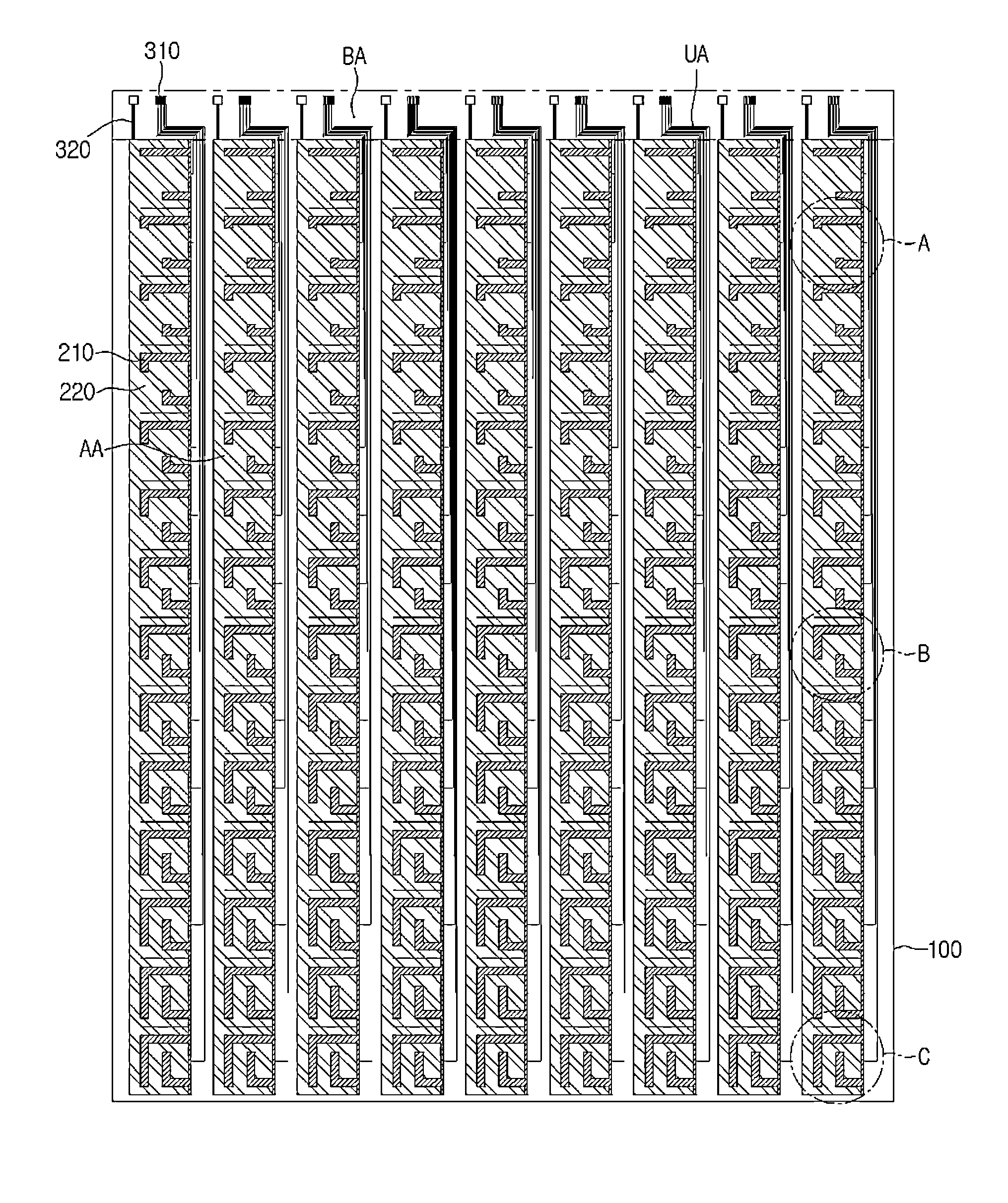
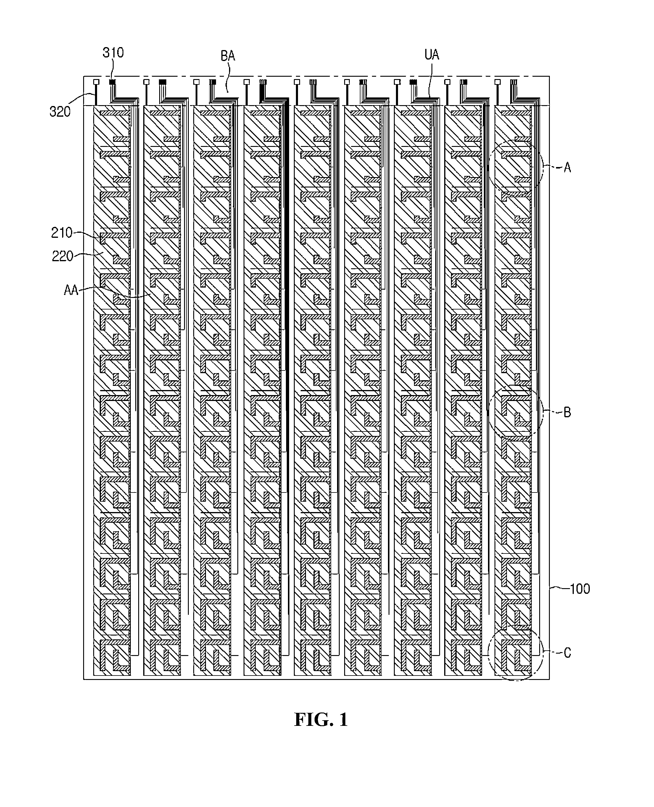
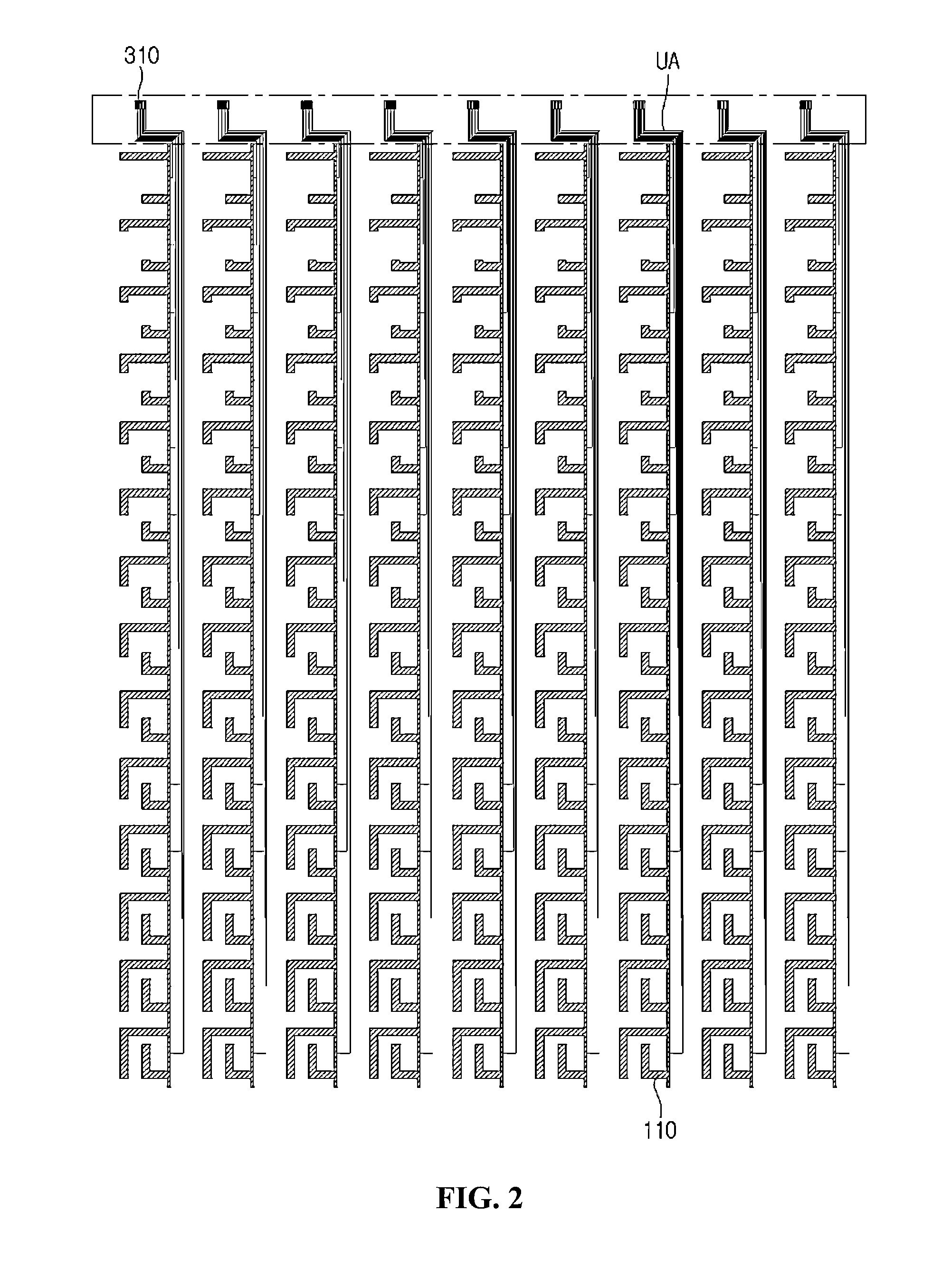
[0025]Hereinafter, the touch panel according to the embodiment will be described in detail with reference to FIGS. 1 to 6.

[0026]FIG. 1 is a view illustrating a touch panel according to an embodiment. Referring to FIG. 1, in th...


PUM


Abstract

A touch panel includes: a cover window in which an active area and an unactive area are defined; a sensing electrode in the active area; a wire electrode connected to the sensing electrode; and a bonding part connected to the wire electrode, wherein the sensing electrode includes a first sensing electrode in the active area; and a second sensing electrode aligned on a same plane with the first sensing electrode in the active area, the first sensing electrode is coupled with the second sensing electrode, and a coupling area between the first sensing electrode and the second sensing electrode is increased as the first sensing electrode and the second sensing electrode are located away from the bonding part.

Description

CROSS-REFERENCE TO RELATED APPLICATION[0001]This application claims the benefit under 35 U.S.C. §119 of Korean Patent Application No. 10-2012-0150796, filed Dec. 21, 2012, which is hereby incorporated by reference in its entirety.BACKGROUND[0002]The embodiment relates to a touch panel.[0003]A touch panel including an input unit (pointing device) has been extensively used in displays of electronic devices such as personal digital assistants (PDA), a notebook computer, office automation (OA) device, a medical device, or an automobile navigation system. For example, a capacitive touch panel, a resistive touch panel, an electromagnetic induction touch panel, and an optical touch panel are generally known in the art. Recently, the resistive touch panel has been extensively used.[0004]A front surface of the touch panel is generally divided into an active area to which a touch command of a user can be input and an unactive area to which the touch command of the user cannot be input. A beze...

Claims


Application Information

Patent Timeline
IPC IPC(8): G02F1/1333
CPCG06F3/0443G06F3/0448G06F3/041G02F1/13338
Inventor CHOE, MIN SU
Owner LG INNOTEK CO LTD
Why Eureka
Try Eureka