Methods for Trimming Polarizers in Displays Using Edge Protection Structures

a technology of edge protection structure and polarizer, which is applied in the manufacture of electrode systems, electric discharge tubes/lamps, instruments, etc., can solve the problems of unsightly visible polarizer edges and peeling of polarizers on the edge of displays

Active Publication Date: 2014-06-26
APPLE INC
View PDF18 Cites 20 Cited by
  • Summary
  • Abstract
  • Description
  • Claims
  • Application Information

AI Technical Summary

Benefits of technology

[0008]To protect display layers such as the color filter layer and the thin-film-transistor layer, a coating is deposited on a peripheral edge of the display layer. A laser is used to cut through portions of the polarizer that overhang the display layer while also cutting th...

Problems solved by technology

If the polarizer is too large, the edge of the polarizer will overhang the edge of the glass display layer, which in turn c...

Method used


Image

  • Methods for Trimming Polarizers in Displays Using Edge Protection Structures
  • Methods for Trimming Polarizers in Displays Using Edge Protection Structures
  • Methods for Trimming Polarizers in Displays Using Edge Protection Structures

Examples


Embodiment Construction

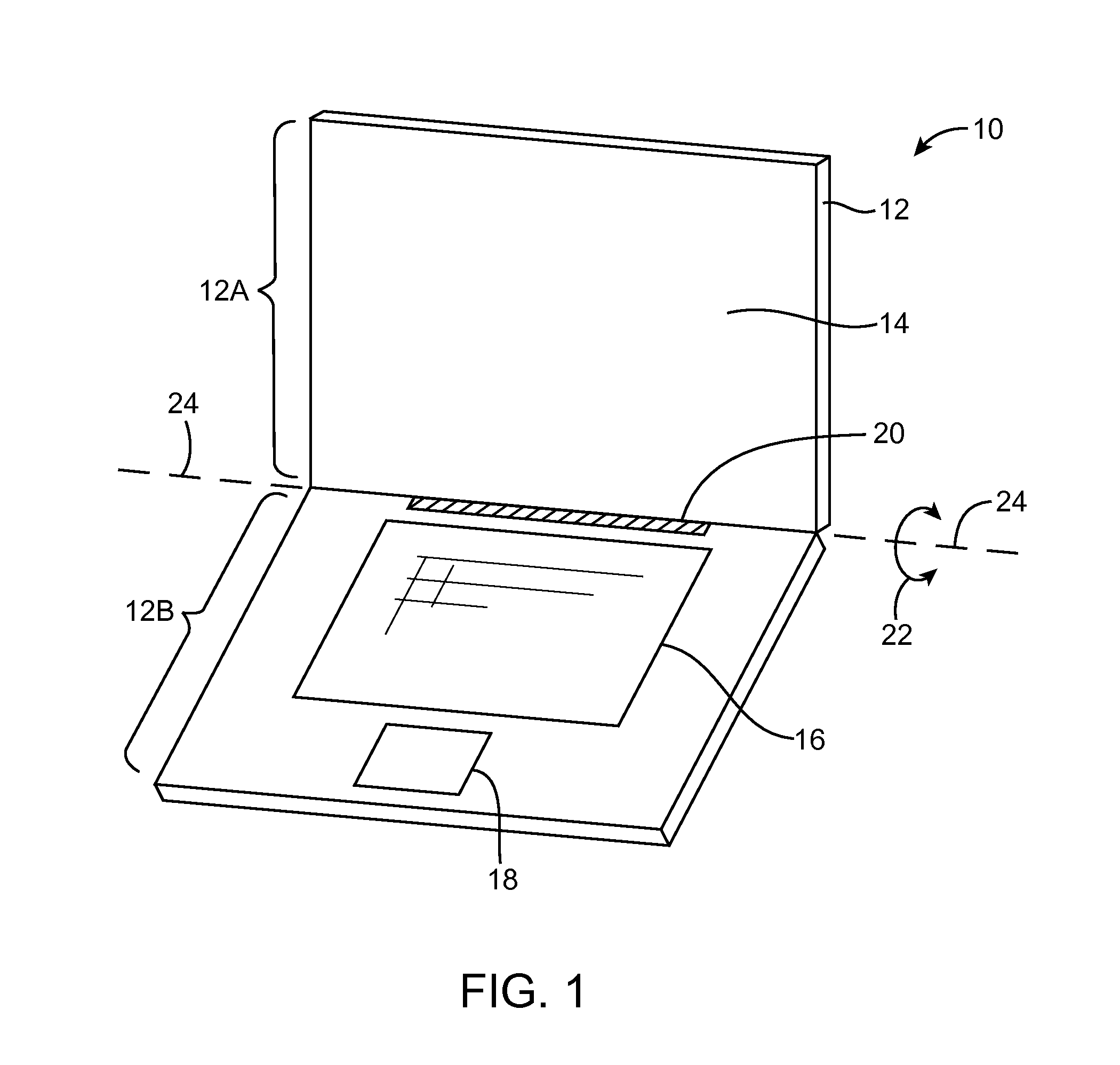
[0031]Displays in electronic devices such as liquid crystal displays may be provided with polarizers. Illustrative electronic devices that have displays with polarizers are shown in FIGS. 1, 2, 3, and 4.

[0032]Electronic device 10 of FIG. 1 has the shape of a laptop computer and has upper housing 12A and lower housing 12B with components such as keyboard 16 and touchpad 18. Device 10 has hinge structures 20 to allow upper housing 12A to rotate in directions 22 about rotational axis 24 relative to lower housing 12B. Display 14 is mounted in upper housing 12A. Upper housing 12A, which may sometimes referred to as a display housing or lid, is placed in a closed position by rotating upper housing 12A towards lower housing 12B about rotational axis 24.

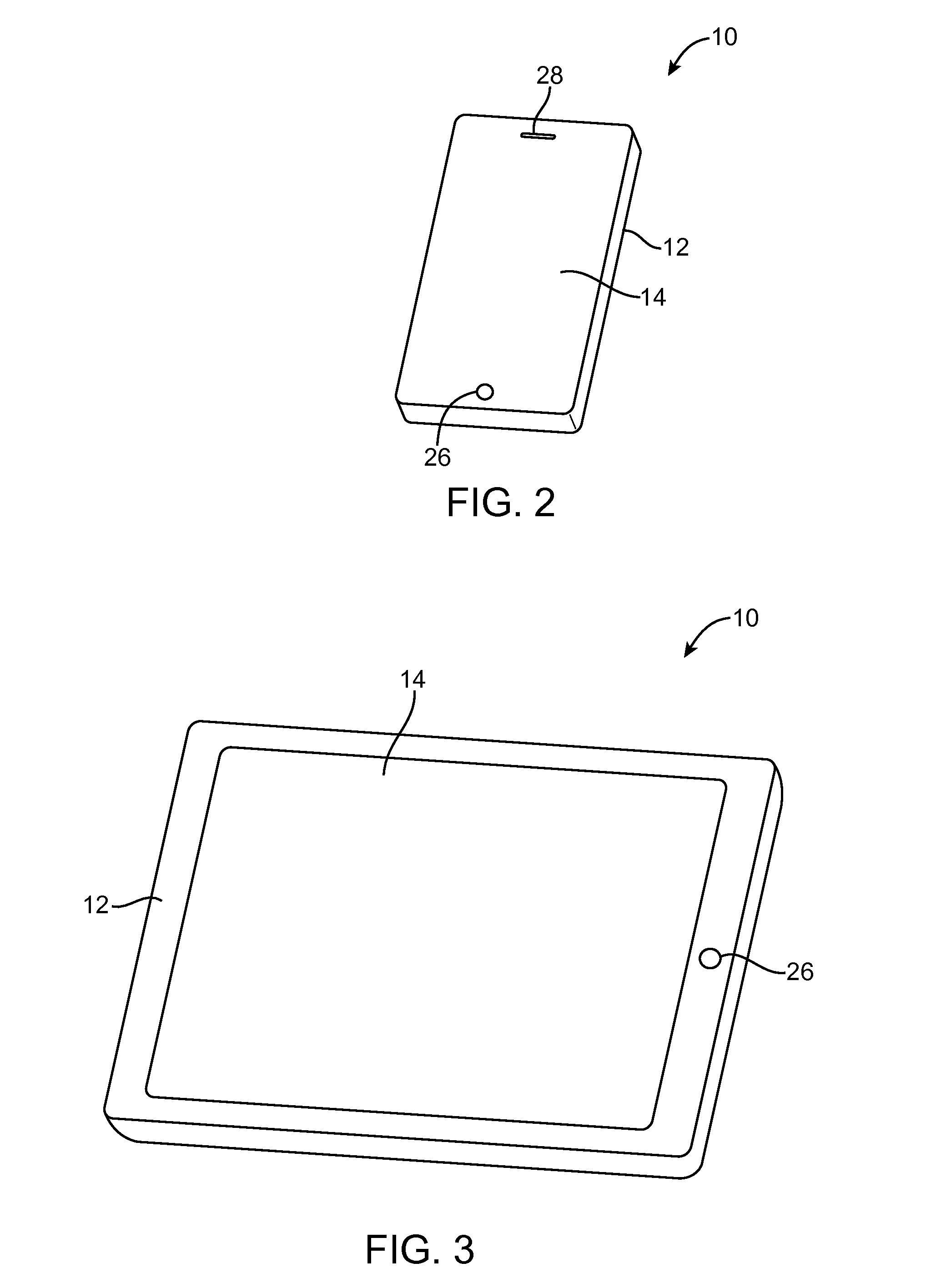
[0033]FIG. 2 shows an illustrative configuration for electronic device 10 based on a handheld device such as a cellular telephone, music player, gaming device, navigation unit, or other compact device. In this type of configuration for devic...


PUM

PropertyMeasurementUnit
Surfaceaaaaaaaaaa

Abstract

An electronic device is provided with a display such as a liquid crystal display. The display has a layer of liquid crystal material sandwiched between an upper display layer such as a color filter layer and a lower display layer such as a thin-film-transistor layer. An upper polarizer is formed on the upper surface of the color filter layer. A lower polarizer is formed on the lower surface of the thin-film-transistor layer. To protect display layers such as the color filter layer and the thin-film-transistor layer, a coating is deposited on a peripheral edge of the display layer. A laser is used to cut through portions of the polarizer that overhang the display layer while also cutting through the coating on the peripheral edge of the display layer. Following laser trimming operations, the coating is flush with an edge surface of the polarizer.

Description

[0001]This application claims priority to U.S. provisional patent application No. 61 / 745,117 filed Dec. 21, 2012, which is hereby incorporated by reference herein in its entirety.BACKGROUND[0002]This relates generally to electronic devices and, more particularly, to electronic devices with displays.[0003]Electronic devices often include displays. For example, cellular telephones and portable computers often include displays for presenting information to a user.[0004]Displays such as liquid crystal display have polarizers. The polarizers are formed from polymer layers that are laminated to glass display layers. It may be desirable to ensure that a polarizer layer has the same size as an associated glass display layer. If the polarizer is too large, the edge of the polarizer will overhang the edge of the glass display layer, which in turn can lead to polarizer peeling. If the polarizer is too small, the edge of the display will have an unsightly visible polarizer edge. Although the po...

Claims


Application Information

Patent Timeline
IPC IPC(8): G02F1/1333
CPCG02F1/133308G02F1/133351B23K26/361B32B2255/00C03B33/0222C03B33/07C03B33/074C03B33/076G02F1/133528
Inventor GUPTA, NATHAN K.HASSAN, MOHD FADZLI A.LIN, KUAN-YINGCHEN, YU-CHENG
Owner APPLE INC
Why Eureka
Try Eureka