Systems and methods for suppressing resonances in power converters

a power converter and resonance suppressing technology, applied in the field of power converters, can solve problems such as overheating and/or malfunction of various converter components, and achieve the effect of suppressing resonances

Inactive Publication Date: 2014-06-26
GENERAL ELECTRIC CO
View PDF3 Cites 3 Cited by
  • Summary
  • Abstract
  • Description
  • Claims
  • Application Information

AI Technical Summary

Benefits of technology

[0004]In one aspect, a power converter is provided. The power converter includes an input stage configured to receive alternating current (AC), an output stage configured to output AC, a first direct current (DC) bus coupling the input stage to the output stage, a second DC bus coupling the input stage to the output stage, a first capacitor leg coupling the first DC bus to the second DC bus, a second capacitor leg coupling the first DC bus to the second DC bus, the first DC bus, the second DC bus, the first capacitor leg, and the second capacitor leg form a current loop having an effective inductance, and at least one resistor configured to suppress a resonance of the power converter, wherein the resonance is based at least in part on the effective inductance of the current loop.
[0005]In another aspect, a system for suppressing resonances in a power converter is provided. The system includes an alternating current (AC) source, an AC load, and a power converter. The power converter includes an input stage configured to receive AC, an output stage configured to output alternating current AC, a first direct current (DC) bus coupling the input stage to the output stage, a second DC bus coupling the input stage to the output stage, a first capacitor leg coupling the first DC bus to the second DC bus, a second capacitor leg coupling the first DC bus to the second DC bus, the first DC bus, the second DC bus, the first capacitor leg, and the second capacitor leg form a current loop having an effective inductance. The power converter further includes at least one resistor configured to suppress a resonance of the power converter, wherein the resonance is based at least in part on the effective inductance of the current loop.

Problems solved by technology

Operating a power converter at or near a resonant frequency, or with harmonics that are at or near a resonant frequency, may cause large ripple currents to be generated, which may cause various converter components to overheat and / or malfunction.

Method used


Image

  • Systems and methods for suppressing resonances in power converters
  • Systems and methods for suppressing resonances in power converters
  • Systems and methods for suppressing resonances in power converters

Examples


Embodiment Construction

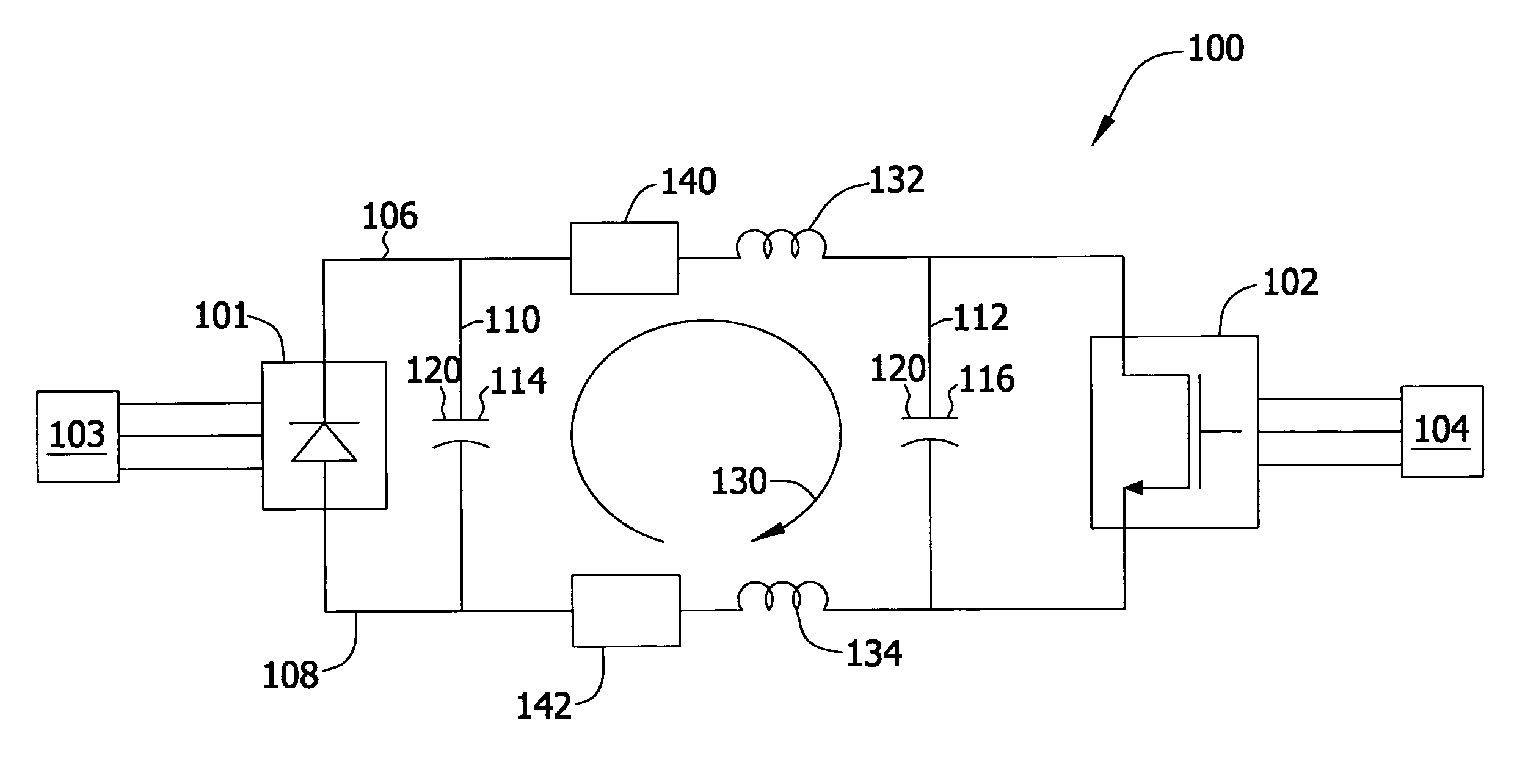
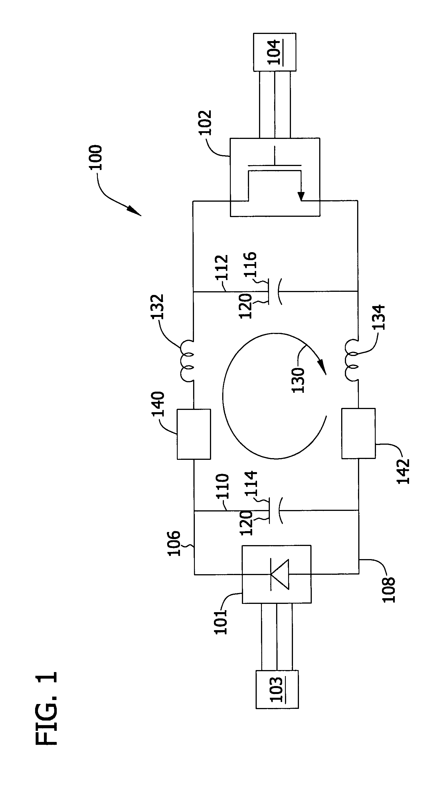
[0015]The methods and systems described herein facilitate suppressing resonances in power converters. Power converters including distributed direct current (DC) links may produce non-trivial inductances and may effectively act as inductor-capacitor (LC) circuits with corresponding resonant frequencies. Damping resistors are included at various locations within the power converter to facilitate suppressing the resonances produced by effective LC circuits. Suppressing resonances using the systems and methods described herein facilitates stabilizing operation of the power converter, and facilitates reducing the likelihood of damage to and / or malfunction of the power converter.

[0016]FIG. 1 is a schematic diagram of an exemplary power converter 100. In the exemplary embodiment, power converter 100 is a non-reversible, or unidirectional, power converter that includes an input stage 101 that receives alternating current (AC), and an output stage 102 that outputs AC. More specifically, in t...


PUM


Abstract

Systems and methods for suppressing resonances in power converters are provided. A power converter (100) includes an input stage (101) configured to receive alternating current (AC), an output stage (102) configured to output alternating current (AC), a first direct current (DC) bus (106) coupling the input stage (101) to the output stage (102), a second DC bus (108) coupling the input stage (101) to the output stage (102), a first capacitor leg (110) coupling the first DC bus (106) to the second DC bus (108) and a second capacitor leg (112) coupling the first DC bus (106) to the second DC bus (108). The first DC bus (106), the second DC bus (108), the first capacitor leg (110), and the second capacitor leg (112) form a current loop (130) having an effective inductance, and at least one resistor (140,142) configured to suppress a resonance of the power converter (100), wherein the resonance is based at least in part on the effective inductance of the current loop.

Description

BACKGROUND OF THE INVENTION[0001]The subject matter disclosed herein relates generally to power converters including two converter sections tied together with a capacitive DC link, and more specifically, to systems and methods for use in suppressing resonances in such power converters.[0002]At least some known power converters are used to convert fixed frequency alternating current (AC) to variable-frequency AC, or vice-versa. To minimize dimensions and reduce losses, at least some known power converters include a tightly-coupled DC link in which an input of the second power converter stage is located relatively close to an output of the first power converter stage. As such, the DC busses connecting the input to the output extend a relatively short distance.[0003]However, in at least some known distributed DC link power converters, the power converter input stage is spaced a considerable distance from the power converter output stage. Because of the distance between the input and th...

Claims


Application Information

Patent Timeline
Patent Type & Authority Applications(United States)
IPC IPC(8): H02M5/42
CPCH02M1/14H02M5/458H02M5/42
Inventor LINDHOLM, BRIAN ERICHARBOURT, CYRUS DAVIDZHANG, RICHARD S.ZHANG, YINGQIZHANG, FAN
Owner GENERAL ELECTRIC CO
Why Eureka
Try Eureka