
Press-fit terminal for board connector and fixing structure of press-fit terminal to connector housing

a technology of press-fit terminal and connector housing, which is applied in the direction of coupling device connection, securing/insulating coupling contact member, electrical apparatus, etc., can solve the problems of large through hole diameter, large pitch of through hole, and possible peeling of plating on the surface of the terminal to generate a soldering failure so as to prevent the peeling of the rear leg part, reduce the pitch of through hole, and minimize the effect of board siz

Inactive Publication Date: 2014-06-26
YAZAKI CORP
View PDF10 Cites 6 Cited by
  • Summary
  • Abstract
  • Description
  • Claims
  • Application Information

AI Technical Summary

Benefits of technology

The patent aims to provide a press-fit terminal for a board connector and a fixing structure of a press-fit terminal to a connector housing that can prevent a plating of a rear leg part from peeling during a press-fit operation and can reduce a diameter of a through hole for soldering the rear leg part so that a circuit may be integrated and a circuit board may be miniaturized.

Problems solved by technology

In that case, however, the diameter of the through hole is liable to be large.
As a result, it is recognized that a pitch of the through hole is large, which is an obstacle to an integration of a circuit or a miniaturization of a circuit board.
Further, it is recognized that when the terminal is press-fitted to the press-fit hole of the connector housing, if the rear leg part is firstly inserted into the press-fit hole, the rear leg part rubs an inner wall of the press-fit hole so that a plating on the surface of the terminal may possibly peel to generate a soldering failure when the rear leg part is soldered.

Method used


Image

  • Press-fit terminal for board connector and fixing structure of press-fit terminal to connector housing
  • Press-fit terminal for board connector and fixing structure of press-fit terminal to connector housing
  • Press-fit terminal for board connector and fixing structure of press-fit terminal to connector housing

Examples


Embodiment Construction

[0029]Now, an embodiment of the present invention will be described below by referring to the drawings.

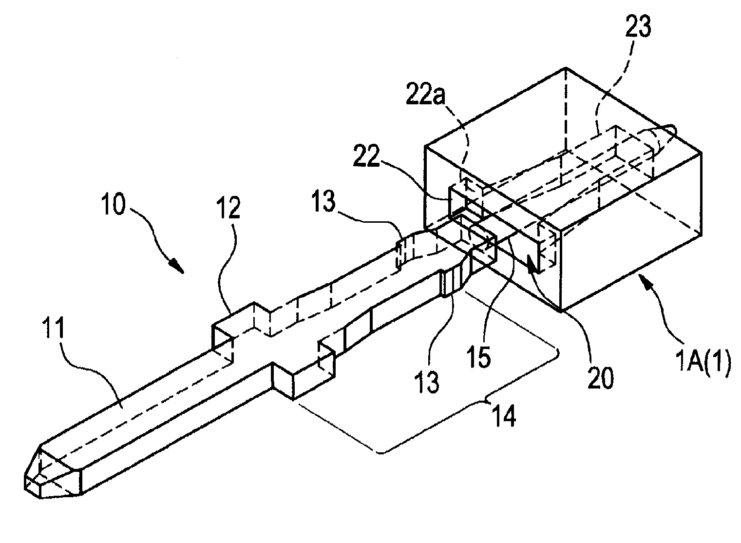
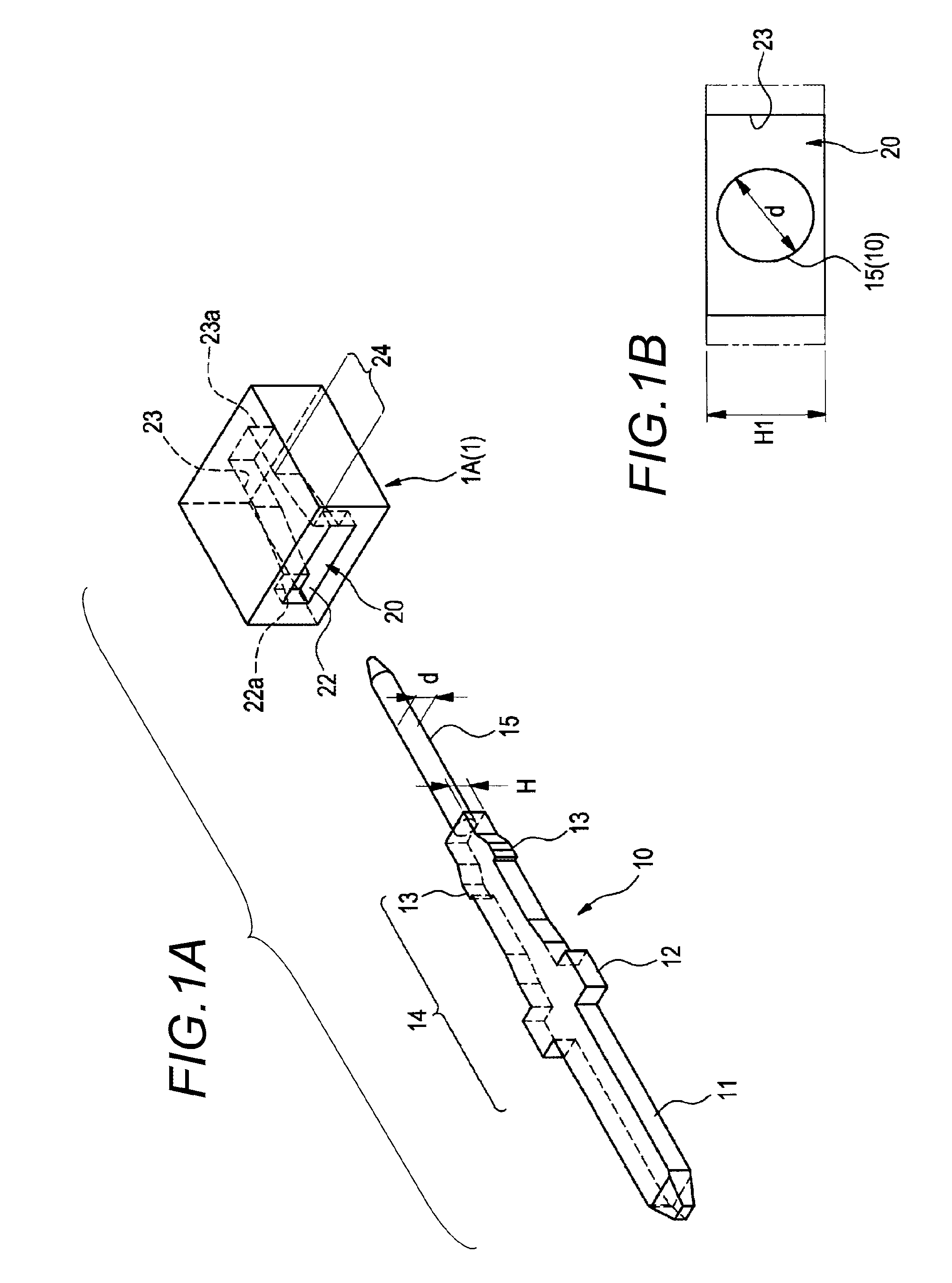
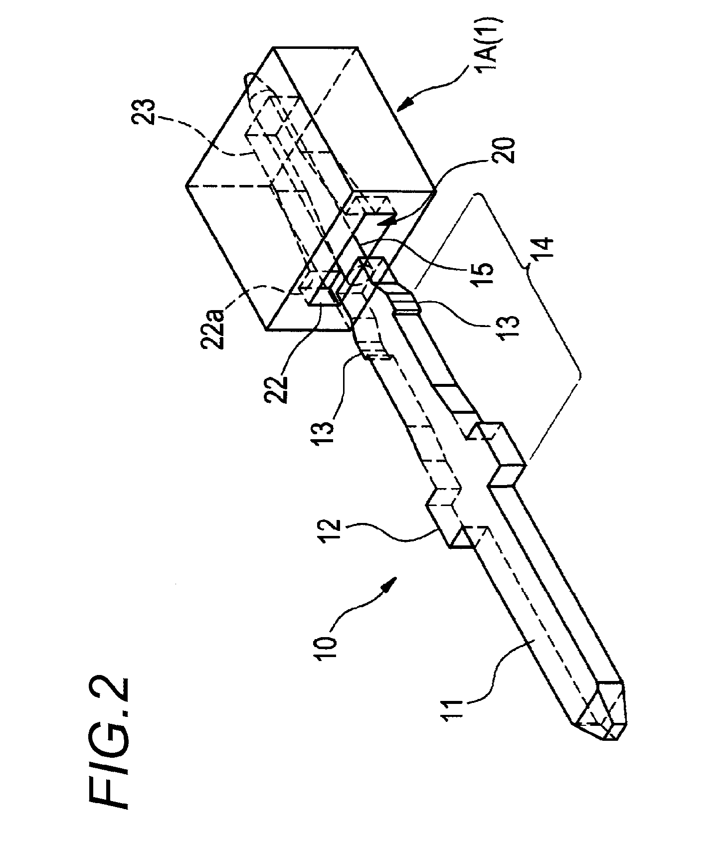
[0030]FIG. 1A is a perspective view showing a state before a press-fit terminal is press-fitted to a press-fit hole formed in a wall part (only a part of the wall part is shown) of a connector housing. FIG. 1B is a diagram seen from a front side of the press-fit hole and showing a dimensional relation between a rear leg part of the press-fit terminal and the press-fit hole. FIG. 2 is a perspective view showing a state when the rear leg part of the press-fit terminal begins to be inserted into the press-fit hole of the connector housing. FIG. 3 is a perspective view showing a state that the press-fit terminal is press-fitted and fixed to the press-fit hole of the connector housing.

[0031]A press-fit terminal 10 according to the embodiment is formed, as shown in FIG. 1A, of a metal member (copper, aluminum, aluminum alloy or the like) which is formed in the shape of a pin as a whole, ...


PUM


Abstract

A press-fit terminal includes an electric connecting part provided in a front part of the press-fit terminal to be electrically connected to a mating connector terminal; a rear leg part provided in a rear part of the press-fit terminal to be inserted and fixed to a through hole of a circuit board; and an engaging part provided in an intermediate part between the electric connecting part and the rear leg part to be press-fitted to a press-fit hole of a wall part of a connector housing. The rear leg part is formed in a shape of a round pin having a circular form in cross-section. The rear leg part may be designed to have a diameter in cross-section being smaller than a minimum dimension between opposed inner wall surfaces of the press-fit hole of the connector housing.

Description

CROSS REFERENCE TO RELATED APPLICATIONS[0001]This application is a continuation of PCT application No. PCT / JP2012 / 071741, which was filed on Aug. 22, 2012 based on Japanese Patent Application (No. 2011-186285) filed on Aug. 29, 2011, the contents of which are incorporated herein by reference.BACKGROUND OF THE INVENTION[0002]1. Field of the Invention[0003]The present invention relates to a press-fit terminal for a board connector and a fixing structure of the press-fit terminal to a connector housing.[0004]2. Description of the Related Art[0005]A board connector is known, for example, in JP-A-2006-100231 that a terminal is press-fitted and fixed to a press-fit hole formed in a wall part of a connector housing. In this kind of connector, the press-fit hole is formed which passes through in a back and forth direction of the rear wall of the connector housing that is made of a resin. A pin shaped male terminal is press-fitted to the press-fit hole, so that the press-fit terminal is fixe...

Claims


Application Information

Patent Timeline
IPC IPC(8): H01R13/42
CPCH01R12/585H01R13/42
Inventor SUZUKI, ETSUROUKONDO, YASUHARU
Owner YAZAKI CORP
Learn More