Method of controlling a device allowing a user to walk or run on the spot in an arbitrary direction and device therefor

a technology of a user's walking or running spot and a control method, which is applied in the direction of movement coordination devices, cardiovascular exercise devices, sports apparatus, etc., can solve the problems of hardly any use of accelerometers used in the known method, the risk of clothing getting entangled in a hazardous way, and the practical drawbacks of known devices

Inactive Publication Date: 2014-06-26
MSE OMNIFINITY AB
View PDF8 Cites 13 Cited by
  • Summary
  • Abstract
  • Description
  • Claims
  • Application Information

AI Technical Summary

Benefits of technology

[0008]According to the invention the first object is achieved by means of a method according to the preamble further characterized by the following steps: mounting a plurality of video cameras above the device on a height well above a user thereof, said cameras being arranged in a defined matrix and directed downwardly; providing a direction indicating marker on top of said user; monitoring the position and size of said marker by means of said cameras; controlling the speed of the roller conveyors depending on said markers distance from said central platform as seen from above by said cameras at an elevated speed when said distance is large and at a lower speed when said distance is small; and halting the roller conveyors when said distance is nil. By using video cameras instead of accelerometers, like in the prior art device, the user only has to wear a simple marker, e.g. on top of a cap or helmet, to get connected to the device. Thus, there is no need of wiring or fitting battey packs or the like, which enhances both convenience and safety. Further, by placing the marker on top of the user instead of on his arm or legs, which are moving to and fro while walking or running, monitoring of the users actual position and adapting the roller conveyor speed thereto becomes more safe and a lot easier.
[0009]The method according to the invention preferably comprises the further step of halting the roller conveyors when the size of said marker as seen from above by said cameras is substantially decreased or when the marker can no longer be seen at all by said cameras. This step marks another important safety feature, because it ensures that the roller conveyors of the device according to the invention come to an immediate halt should the user kneel or lie down or trip and fall or just lose the marker.
[0010]The method according to the invention preferably comprises the further steps of mounting video displays or screens, that can be viewed by the user, and of adapting the content shown on said video displays or screens to the speed of the roller conveyors, the actual position and size of said marker and to its direction. This makes it possible to greatly enhance the users overall perception in a virtual reality environment created by means of said video displays or screens. Further, according to a preferred embodiment the theme to be shown on said video displays or screens can be chosen depending on the type of marker used. This makes the device according to the invention more user friendly and adaptable, for instance by simply changing from one cap, having one type of marker thereon, to another cap, having another typ of marker thereon.
[0012]According to the invention the second object is achieved by means of a device for allowing a user to walk or run on the spot in an arbitrary direction, the device comprising a stationary central platform surrounded by a convex polygon shaped deck in level therewith, said deck being divided into trapezoid shaped roller conveyors, wherein each conveyor has rollers in parallel with the trapezoid bases, the shorter one of these adjoining said platform and the longer one of these forming a side of said polygonal shape, and wherein the rollers of said conveyors are driven in order to move a user stepping thereon back to said central platform, wherein said rollers are continuous circular cylindrical, and wherein beneath each conveyor there is a driving means for frictional driving engagement with said rollers from below, said device being characterized in that said driving means comprises an endless belt extenting along the roller conveyor in frictional driving engagement with all rollers thereof, and in that said driving means frictionally engages the conveyor rollers in a central part of these, said rollers being journalled at end parts thereof in resiliently mounted bearings. Compared to WO 96 / 35481 A2 this facilitates not only the production and mounting of the trapezoid roller conveyors and their rollers, but also service measures, because for example no driving belts have to be dismantled in order to lift off a conveyor. Further the device according to the invention improves safety in that the roller conveyor surfaces become smoother and less rugged than before, thereby reducing risk of clothing entanglement or finger sqeezing. Further, compared to WO 2010 / 089618 A2 a device according to the invention is much easier to accomplish than a drive solution comprising individual rubber wheels, and the built in resiliency of the device according to the invention makes the roller conveyor more pleasant to walk or run upon, just like a slightly resilient sporting floor, and assures good driving contact between the rolls of a conveyor and said driving means even if a user steps on rolls far from the central parts of these.
[0015]Preferably said floor plate covers parts of said driving means. This is very advantageous, because it simplyfies access to the driving means. Further, it makes it possible to minimise height of the device, because for example the preferred single motor, which has to be of considerable size, thus can be hidden below the rather thin floor plate instead of below a rather thick roller conveyor.

Problems solved by technology

For one thing, the waist part of the rollers increases risk of a user's clothing getting entangled in a hazardous way, even if said waist part, as indicated, is partly covered by means of a countersunk cover strip.
Furthermore, the accelerometers used for the known method are hardly of any use when it comes to detecting the user stumbling, which for safety reasons would necessitate an immediate halt of the conveyors in order to avoid risk of squeezing for instance a finger.
Then the known device has some practical drawbacks, too.
The mounting of the rollers is rendered quite complicated by the way chosen to drive the rollers, regardsless if a belt is used, encompassing the rollers and thus hampering their mounting or dismounting, or cog wheels are used, necessitating use of intermediate gears in order to get neighboring rollers rotate in the same and not opposite directions.
Further, the use of distance measuring sensor means arranged on a circumferential railing does not render it possible to control the device safely for instance when a user kneels or stumbles and falls.

Method used


Image

  • Method of controlling a device allowing a user to walk or run on the spot in an arbitrary direction and device therefor
  • Method of controlling a device allowing a user to walk or run on the spot in an arbitrary direction and device therefor
  • Method of controlling a device allowing a user to walk or run on the spot in an arbitrary direction and device therefor

Examples


Embodiment Construction

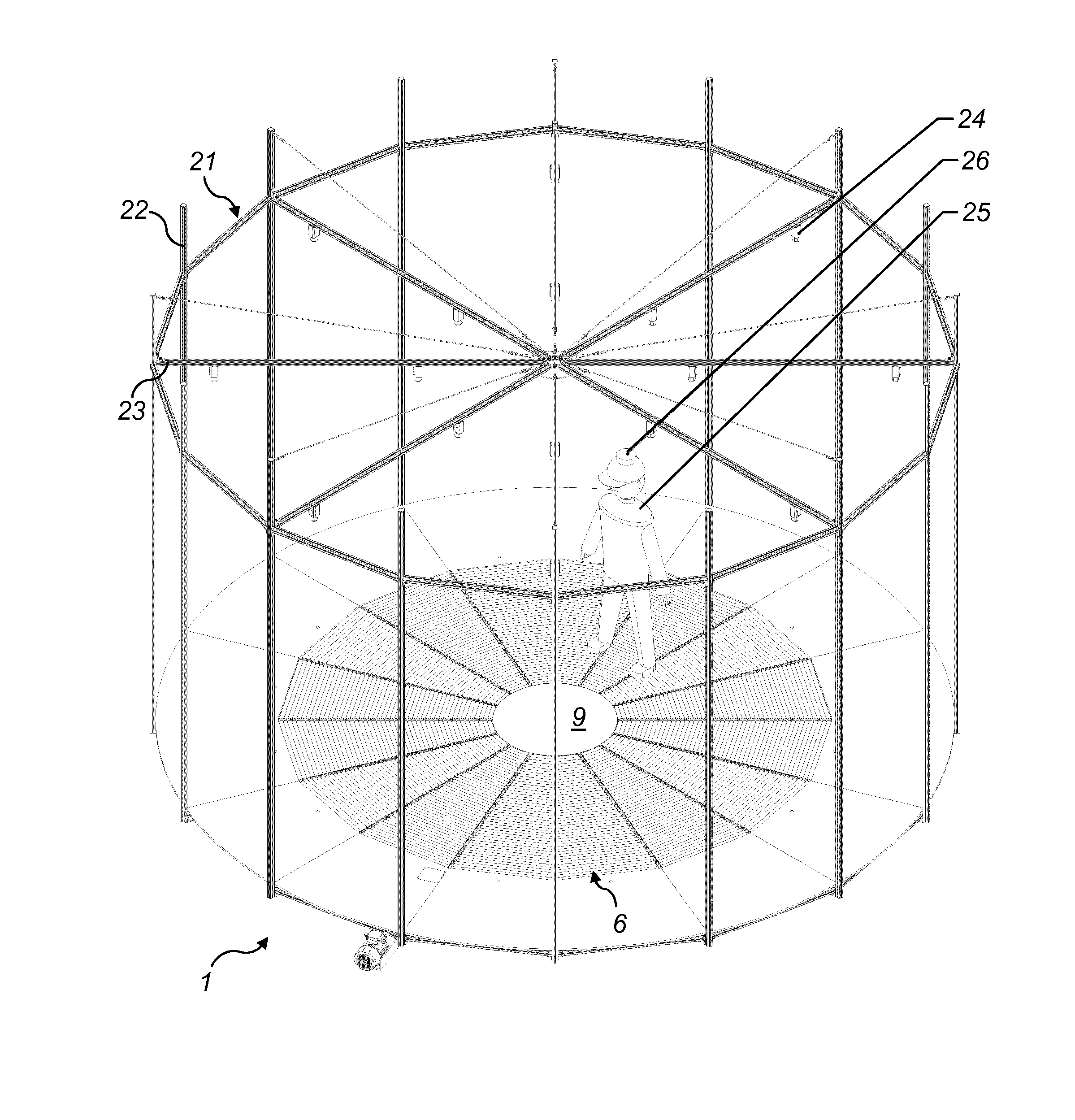
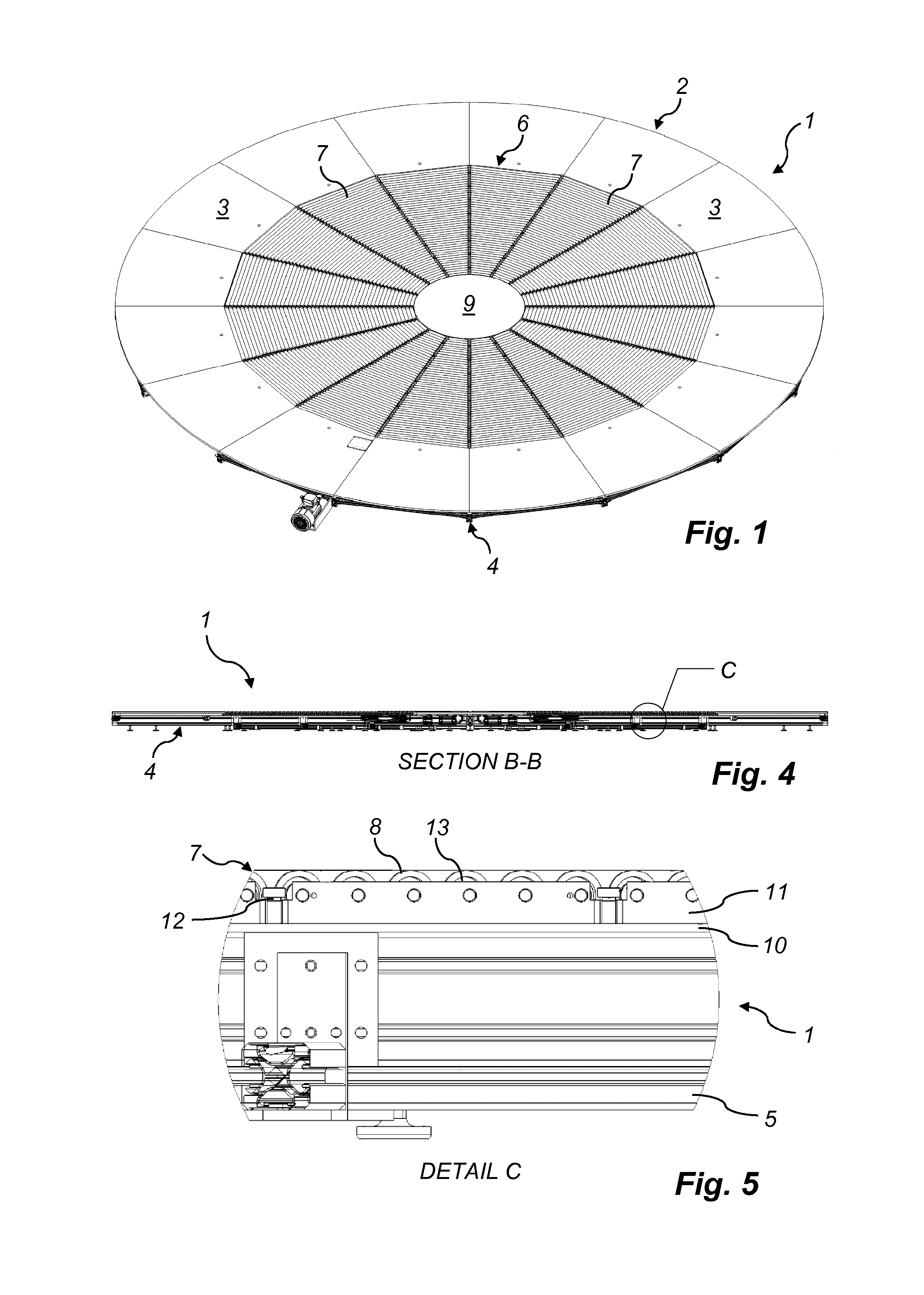
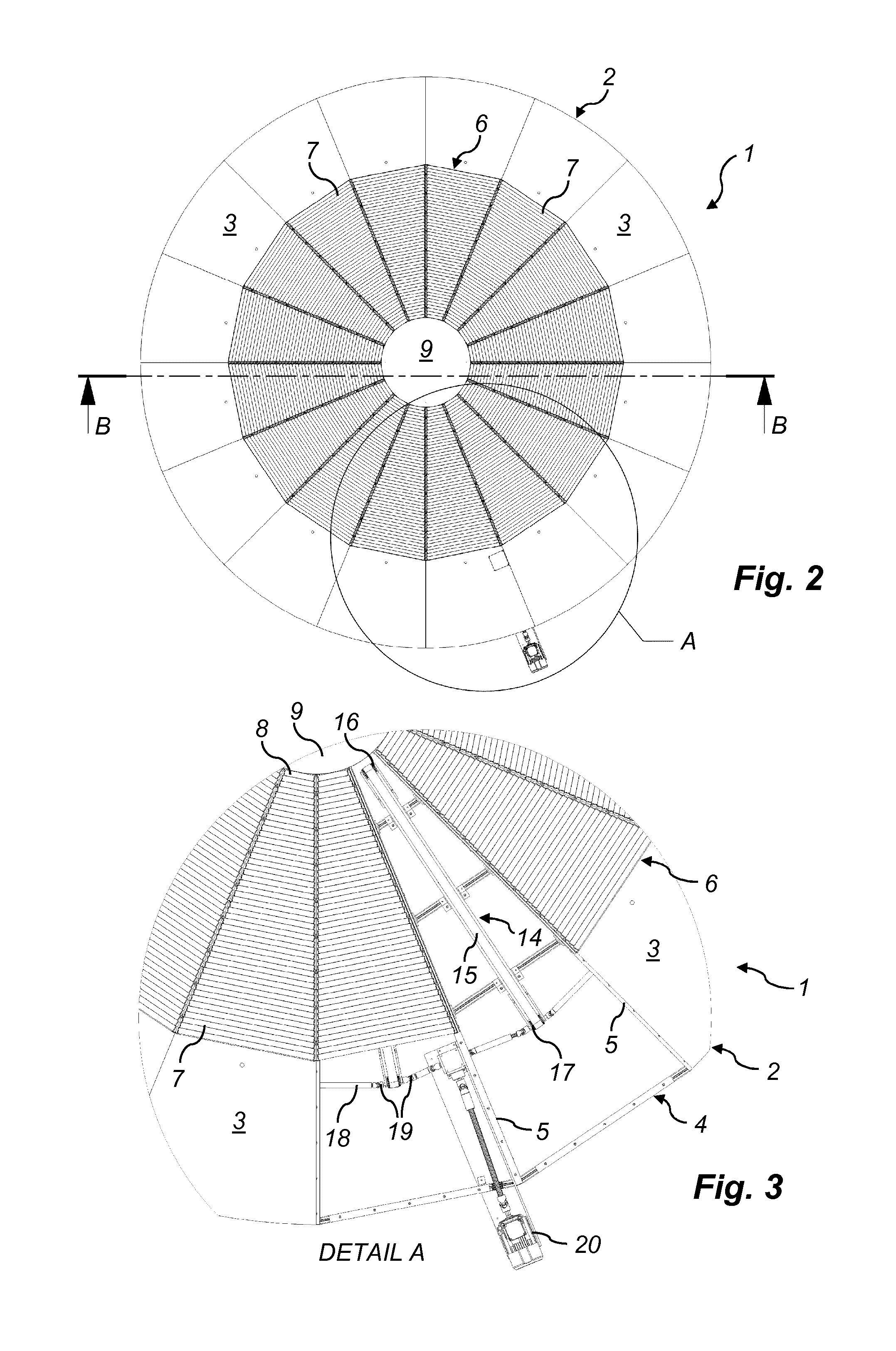
[0024]The device 1 according to the preferred embodiment of the invention is generally circular when seen from above. The circle periphery is created by a horisontal ringshaped floor plate 2, which by radial lines is divided into several sectors 3. In total there are sixteen identical floor sectors 3, all of them resting on a framing structure 4 including radial beams 5 underneath the division lines. The framing structure 4 with its radial beams 5 is best seen in FIG. 3, where two floor sectors 3 are removed to reveal the substructure of the device 1. At the inner circumference of the ringshaped floor plate 2 each floor sector 3 forms a line, that runs straight from one of the division lines to the next. This makes the sixteen floor sectors 3 create a regular hexadecagon shaped ring opening.

[0025]Inside of the ring opening of the ring shaped floor plate 2 a horisontal deck 6 is provided in level with the floor plate 2. The deck 6 too is ring shaped and concentric with the floor plat...


PUM


Abstract

The invention concerns a method for controlling a device (1) allowing a user (25) to walk or run on the spot in an arbitrary direction and a device (1) therefor. The device (1) comprises a stationary central platform (9) surrounded by a convex polygon shaped deck (6) in level therewith, said deck (6) being divided into trapezoid shaped roller conveyors. Each conveyor has rollers in parallel with the trapezoid bases, the shorter one of these adjoining said platform and the longer one of these forming a side of said polygonal shape. The rollers of said conveyors are driven in order to move a user (25) stepping thereon back to said central platform (9). The rollers as such are continuous circular cylindrical, and beneath them there is a driving belt for frictional driving engagement with the rollers from below. According to the method a marker (26) placed on top of the user (25) is monitored by means of video cameras (24) and the speed of the roller conveyors adjusted depending on the perceived marker size and position.

Description

TECHNICAL FIELD[0001]The present invention concerns a method for controlling a device allowing a user to walk or run on the spot in an arbitrary direction, the device comprising a stationary central platform surrounded by a convex polygon shaped deck in level therewith, said deck being divided into trapezoid shaped roller conveyors, wherein each conveyor has rollers in parallel with the trapezoid bases, the shorter one of these adjoining said platform and the longer one of these forming a side of said polygonal shape, and wherein the rollers of said conveyors are driven in order to move a user stepping thereon back to said central platform. Further, the present invention concerns a device controlled by such a method.PRIOR ART[0002]A device of the kind in question is previously known from the international application WO 96 / 35481 A2. In that application an embodiment of a device is revealed, comprising trapezoid roller conveyors having rollers divided into two equally long circular c...

Claims


Application Information

Patent Timeline
Patent Type & Authority Applications(United States)
IPC IPC(8): A63B24/00A63B22/02
CPCA63B21/15A63B22/02A63B22/0285A63B24/0021A63B24/0087A63B69/0035A63B71/0622A63B2022/0271A63B2024/0025A63B2024/0096A63B2071/0072A63B2071/0081A63B2071/009A63B2071/0644A63B2220/05A63B2220/10A63B2220/806A63B2220/836A63B2225/102A63B2225/15A63B22/025A63B22/0292
Inventor SCHMITZ, MICAELJOHANSSON, DANIEL
Owner MSE OMNIFINITY AB
Why Eureka
Try Eureka