Eureka AIR delivers breakthrough ideas for toughest innovation challenges, trusted by R&D personnel around the world.

Matrix permitivity determination (is10.0565-us-pct)

Active Publication Date: 2014-07-03
SCHLUMBERGER TECH CORP
View PDF3 Cites 8 Cited by
  • Summary
  • Abstract
  • Description
  • Claims
  • Application Information

AI Technical Summary

Benefits of technology

The present invention relates to a method for determining the dielectric permittivity of a porous material. The method involves saturating the material with a fluid composition that changes with temperature, measuring the permittivity of the material at different temperatures, and processing the measurements to determine the extent of changes in the material's thermodynamic properties. The invention also includes a method for separately analyzing the material and the fluid composition, as well as a device for changing the temperature of the material. The technical effects of the invention include improved accuracy in determining the dielectric permittivity of porous materials and improved understanding of the thermodynamic properties of the materials.

Problems solved by technology
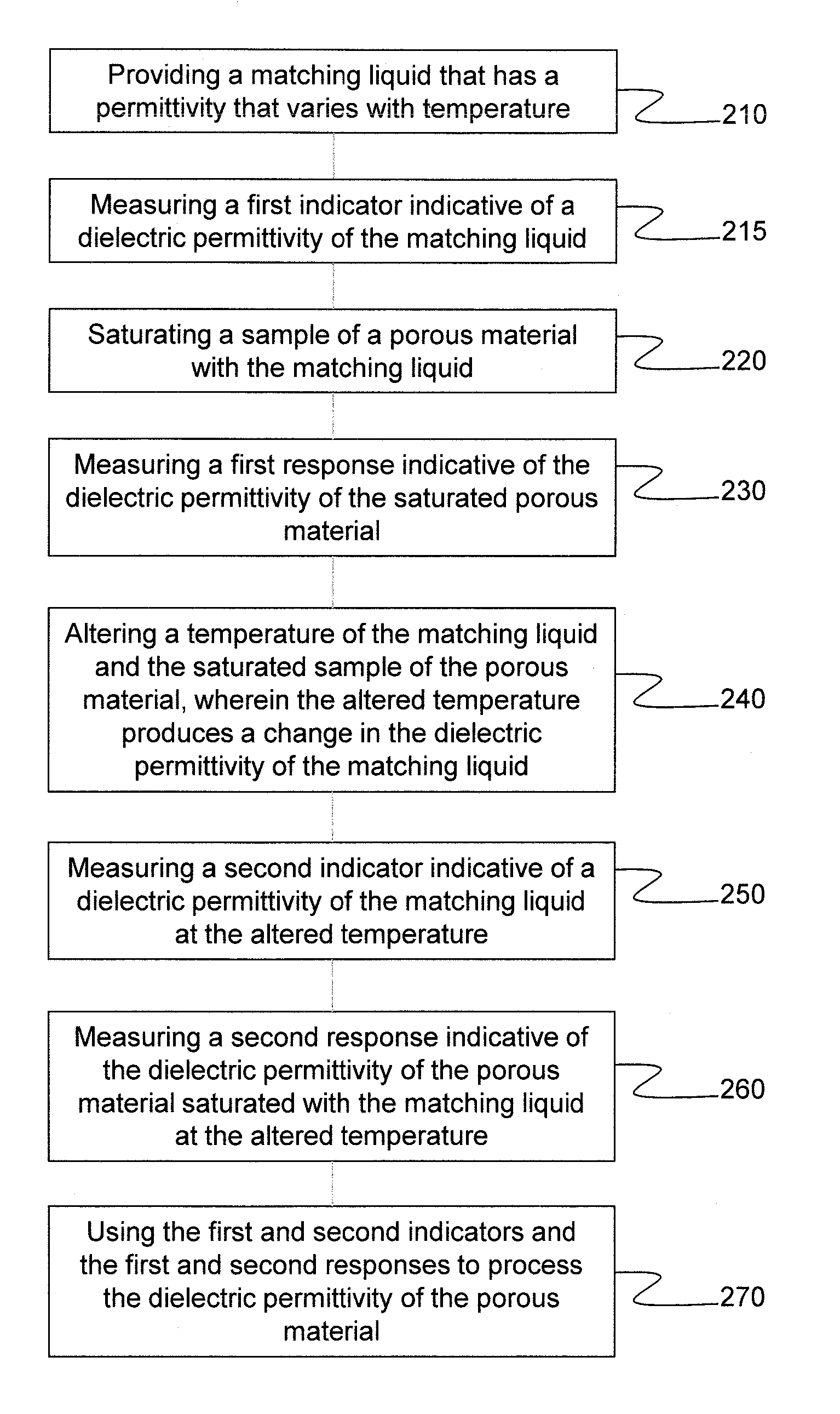
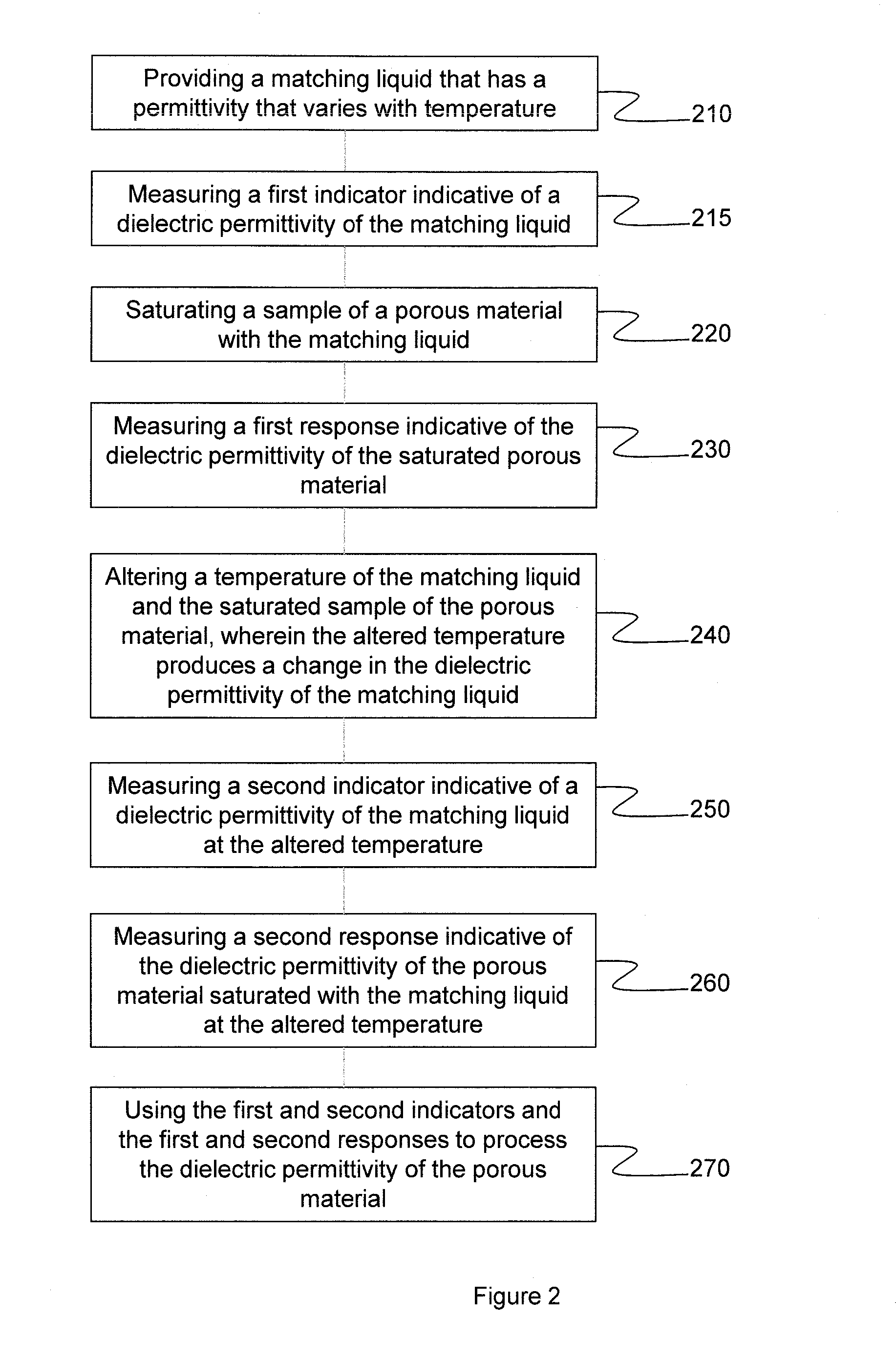
A disadvantage of mixing rules is that they require knowledge of both the matrix and fluid complex permittivity, which knowledge may be difficult to ascertain.
However, obtaining solely the rock matrix permittivity—often termed the “dry rock permittivity”—from such measurements on saturated rock is problematic because of the contribution of the pore space in the rock to the rock matrix permittivity; which contribution cannot be determined from the saturated rock measurement.
A similar problem applies to obtaining the permittivity of the rock matrix from permittivity measurements made on a powdered sample of the rock, e.g. in a measurement system where the grains of the powdered rock sample are suspended in a liquid or gaseous dielectric; the problem arising again from the fact that the permittivity effects of the pore space in the rock matrix cannot be measured from the saturated powder as the fluid saturating the pores mixes the effect of the pores with the measured permittivity.
However, the mixture rules are of unknown validity and can differ markedly from one another, and hence can produce large errors in rock matrix permittivity values that are derived from saturated rock permittivity measurements.

Method used


Image

  • Matrix permitivity determination (is10.0565-us-pct)
  • Matrix permitivity determination (is10.0565-us-pct)
  • Matrix permitivity determination (is10.0565-us-pct)

Examples


Embodiment Construction

[0022]The ensuing description provides preferred exemplary embodiment(s) only, and is not intended to limit the scope, applicability or configuration of the invention. Rather, the ensuing description of the preferred exemplary embodiment(s) will provide those skilled in the art with an enabling description for implementing a preferred exemplary embodiment of the invention. It being understood that various changes may be made in the function and arrangement of elements without departing from the scope of the invention as set forth in the appended claims.

[0023]Specific details are given in the following description to provide a thorough understanding of the embodiments. However, it will be understood by one of ordinary skill in the art that the embodiments maybe practiced without these specific details. For example, circuits may be shown in block diagrams in order not to obscure the embodiments in unnecessary detail. In other instances, well-known circuits, processes, algorithms, stru...


PUM


Abstract

A method and system for determining a rock matrix dielectric permittivity. The method and system use a matching liquid with a temperature dependant permittivity. The matching liquid may be used in an automated and / or downhole system for measuring matrix dielectric permittivity of rock formations.

Description

BACKGROUND OF THE DISCLOSURE[0001]To understand earth formations and how such formations behave, it is necessary to determine the permittivity of the rock comprising the formation. For example, in order to produce hydrocarbons economically, a reasonably accurate estimation of hydrocarbon volume and mobility needs to be performed. The measurement of dielectric constant (or dielectric permittivity) of formations surrounding a borehole is known to provide useful information about the formations for hydrocarbon transport purposes. The dielectric constant of the different materials in earth formations vary widely—for example, dielectric constants are roughly 2.2 for oil, 7.5 for limestone, and 80 for water—so measurement of dielectric properties can be a useful means of formation evaluation.[0002]For hydrocarbon production purposes, effective measurement of formation permittivity and / or conductivity must be performed. The earth formation consists of the rock matrix and the pore fluids—us...

Claims


Application Information

Patent Timeline
IPC IPC(8): G01N15/08E21B49/00
CPCE21B49/00G01N15/08G01N15/088G01N33/24G01N22/00G01N27/221G01R27/2617
Inventor ANDERSON, VALERIEMEETEN, GERALDCLARKE, ANDREWZHANG, TIANHUALIGNEUL, PATRICE
Owner SCHLUMBERGER TECH CORP
Why Eureka
Eureka Blog
Learn More