
Measuring instrument, measurement system, measurement position positioning method and measurement position positioning program using the same

a technology of measurement position and positioning method, which is applied in the direction of instruments, optical radiation measurement, spectrophotometry/monochromators, etc., can solve the problems of insufficient development of the technique for aligning the same measurement point of different measuring targets such as the final proof and the printed material, and cannot accurately check the color reproduction in the picture (image) of printed material. to achieve the effect of accurate alignment of the corresponding measurement poin

Inactive Publication Date: 2014-07-03
PROSPER CREATIVE
View PDF5 Cites 14 Cited by
  • Summary
  • Abstract
  • Description
  • Claims
  • Application Information

AI Technical Summary

Benefits of technology

The invention allows for accurately aligning and evaluating measurement targets from both measurement points.

Problems solved by technology

Thus, it is not possible to accurately check the color reproduction in a picture (image) of the printed material using the color patches only.
However, there is a problem that it is difficult to realize positioning for measuring the same points of a final proof and a printed material.
However, a technique for aligning the same measurement points of different measuring targets such as the final proof and the printed material has not been developed.
However, in this case, the system may become expensive, and an accuracy error will be occurred by expansion and shrinking of paper due to humidity and the like, or caused by the accuracy of an output recorder.
As a result, the size of a final proof and a printed material may be different or a partial dimensional error may occur.
Thus, it is only possible to realize rough positioning with a simple method and it is difficult to obtain stable measurement results.
Furthermore, since the measurement value is different depending on the direction of a picture with respect to a measuring instrument, it is difficult to obtain sufficient measurement accuracy with only the X and Y position control device.

Method used


Image

  • Measuring instrument, measurement system, measurement position positioning method and measurement position positioning program using the same
  • Measuring instrument, measurement system, measurement position positioning method and measurement position positioning program using the same
  • Measuring instrument, measurement system, measurement position positioning method and measurement position positioning program using the same

Examples


first embodiment

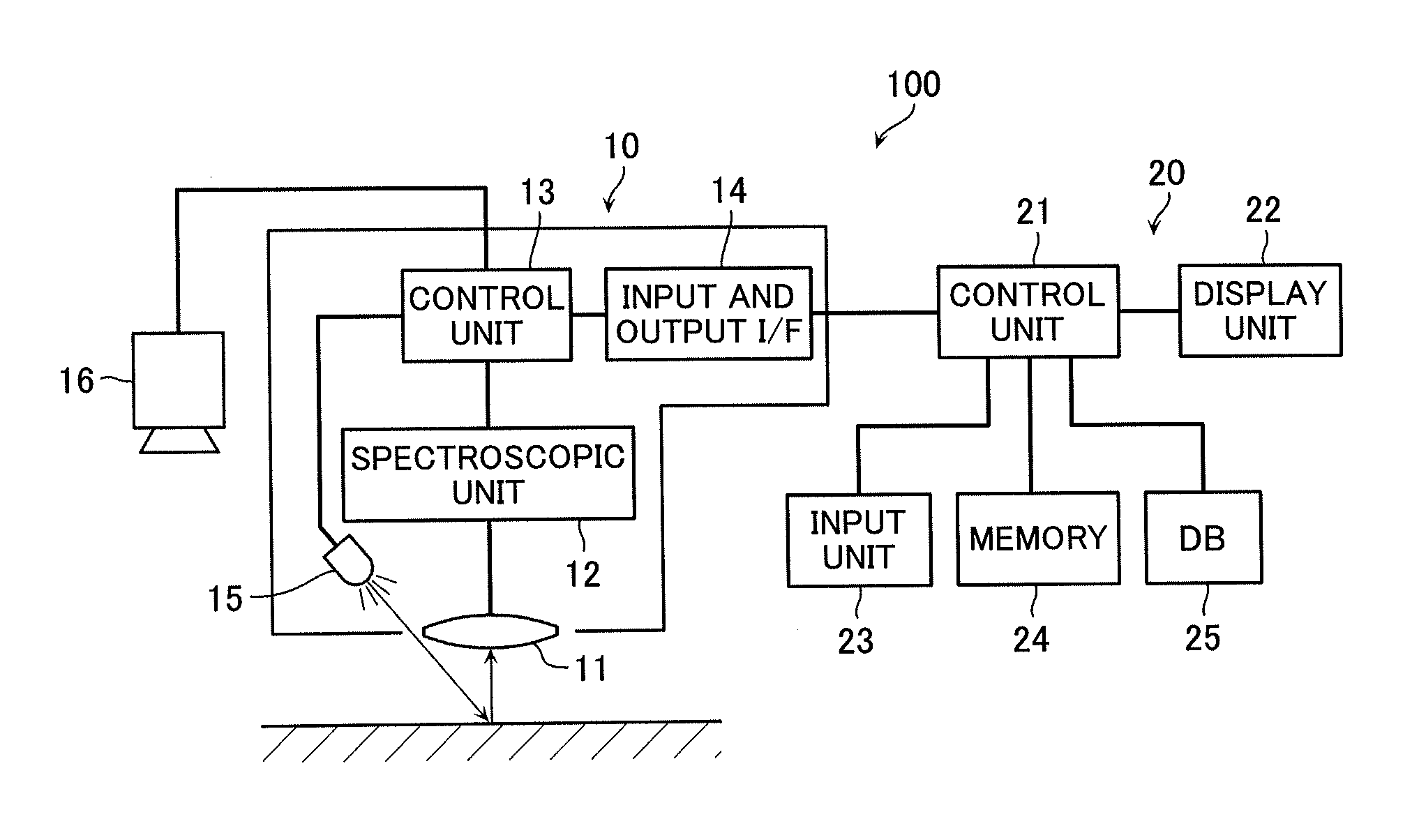
[0068]A first embodiment is an example in which the present invention is applied to an optical measurement system used when performing color-matching between a final proof and a printed material in offset printing or the like. In this example, the measurement target is a “final proof” and a “printed material,” and the former is referred to as a “reference medium” and the latter is referred to as “evaluation medium.”

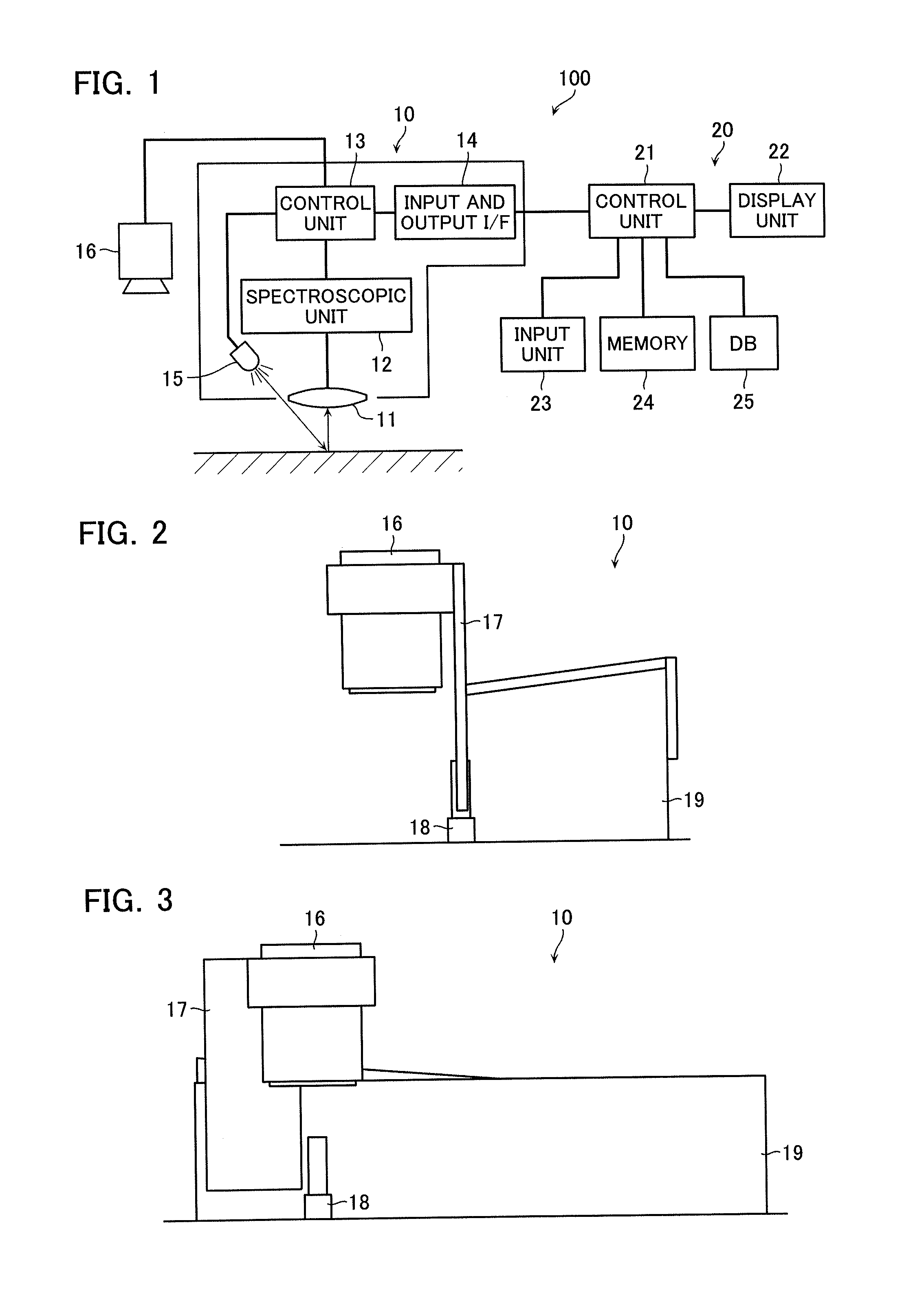
[0069]FIG. 1 is a diagram illustrating an entire configuration of a measurement system according to the first embodiment of the present invention. FIG. 2 is a side view of a measuring instrument of the measurement system and FIG. 3 is a front view. FIG. 4 is a flowchart illustrating the flow of a measurement process of the measurement system.

[0070]As illustrated in FIG. 1, a measurement system 100 is configured to include a measuring instrument 10 and a computer (PC) 20. The measuring instrument 10 includes a lens unit 11, a spectroscopic unit 12, a control unit 13, an in...

second embodiment

[0100]FIG. 10 is a flowchart illustrating the flow of a measurement process of a measurement system according to a second embodiment of the present invention. FIG. 11 is a diagram illustrating an example of a display screen of the measurement system. The measurement system according to the present embodiment has the same configuration as the measurement system 100 according to the first embodiment. The present embodiment is different from the first embodiment in that a reference positioning image serving as a reference point of positioning is added instead of the mark 32.

[0101]As illustrated in FIG. 10, first, the measuring instrument 10 is set so that the measurement aperture 18 is positioned at any measuring point of the reference medium, the color of the measurement point is measured to acquire measurement data including color information or the like, and the camera 16 captures the reference image of the surroundings of the measurement point at the point in time at which the meas...

third embodiment

[0108]As illustrated in FIG. 12, the measuring instrument 10 according to the present invention may be attached to an existing 2 or 3-dimensional position control device 200, for example, to measure colors. The position control device 200 can control the position of the measuring instrument 10 with the aid of movable shafts 201 and 202 so that the measuring instrument 10 can freely move in X and Y directions, as illustrated with arrows in the figure. By doing so, the present invention can be favorably applied to measurement of colors on a printed surface on which ink is not dried as in an evaluation medium such as a printed material immediately after printing without dirt adhering to the measuring instrument 10.

[0109]Moreover, although not illustrated in the drawing, the measurement system may have a configuration in which a measuring instrument is fixed to a predetermined fixing portion and the measurement target is moved by an X and Y-position (automatic) control device. In this c...


PUM


Abstract

A measurement system is capable of accurately aligning the corresponding measurement points of a plurality of measurement targets to evaluate the measurement targets from measurement results. A measurement system includes a measuring instrument and a PC, the measuring instrument includes a spectroscopic unit that measures a measurement point of a measurement target and a camera that images surroundings in real-time. The PC displays an evaluation image of continuous image information, which is imaged and displayed by the camera on a display screen so as to be superimposed on a reference image of still image information, which has been imaged and stored in memory. By comparing the data obtained by measuring the measurement point in the evaluation image when both images overlap each other and the measurement data of the point in the reference image, it is possible to perform positioning easily and compare the measurement data.

Description

TECHNICAL FIELD[0001]The present invention relates to a measuring instrument and a measurement system for measuring a physical quantity of a particular point or area, and a measurement position positioning method and a measurement position positioning program using the same. In particular, the present invention relates to a measuring instrument and a measurement system requiring positioning of the corresponding measurement points of two or more measurement targets, and a measurement position positioning method and a measurement program using the same.BACKGROUND ART[0002]Conventionally, there are various cases where a plurality of measurement targets is accurately aligned in positions in order to evaluate both of the measurement result. The plurality of measurement targets are, for example, a measurement point of a reference measurement target and a measurement point of a measurement target.[0003]For example, in color matching of printed materials by offset printing, in the printing ...

Claims


Application Information

Patent Timeline
Patent Type & Authority Applications(United States)
IPC IPC(8): G06T7/40
CPCG06T7/408G01J3/50G01J3/0291G01J3/0278G01J3/0264G01J3/0289G01J3/0208G01J3/027G01J3/0248G01J3/513G01J3/2823G06T7/90B41F33/0036
Inventor KAWABATA, HIDEKIKIJIMA, AKIRA
Owner PROSPER CREATIVE
Learn More