Optical bench apparatus having integrated monitor photodetectors and method for monitoring optical power using same

a bench apparatus and monitor technology, applied in the field of optical power monitoring, can solve the problems of power monitoring being monolithically integrated and/or heterogeneous integrated, the method may not scale well to parallel modules with a small form factor, etc., and achieves the effect of improving alignment tolerance, small size, and fast photodetector

Active Publication Date: 2014-07-03
ZEPHYR PHOTONICS
View PDF5 Cites 6 Cited by
  • Summary
  • Abstract
  • Description
  • Claims
  • Application Information

AI Technical Summary

Benefits of technology

[0066]An advantage of the invention may be to provide an optical bench apparatus in which a smaller, faster photodetector may be used.
[0067]Another advantage of the invention may be to provide an optical bench apparatus to improve alignment tolerances.
[0068]A further advantage of the invention may be to provide an optical bench apparatus having one or more lenses formed on the side opposite the light transmitter. The lenses may be refractive and / or diffractive. The lenses collimate the output from the light transmitter, focus the output from the light transmitter and / or steer the output from the light transmitter.
[0069]Another advantage of the invention may be to provide a method of monitoring optical power having the step of optimizing bias and / or modulation currents to achieve desired operating characteristics of the transmitter and / or an optical link.
[0070]Yet another advantage of the invention may be to provide a method having the step of adjusting operating characteristics of the transmitter for temperature variations and / or degradation by optimizing bias and / or modulation currents.
[0071]Still another advantage of the invention may be to provide a method having the step of implementing health monitoring and / or built-in test functions in a transceiver by monitoring the transmitted power and / or received power in an optical link.

Problems solved by technology

Further, the method may not scale well to parallel modules with a small form factor.
For example, such a method of optical power monitoring may be monolithically integrated and / or heterogeneously integrated.

Method used


Image

  • Optical bench apparatus having integrated monitor photodetectors and method for monitoring optical power using same
  • Optical bench apparatus having integrated monitor photodetectors and method for monitoring optical power using same
  • Optical bench apparatus having integrated monitor photodetectors and method for monitoring optical power using same

Examples


Embodiment Construction

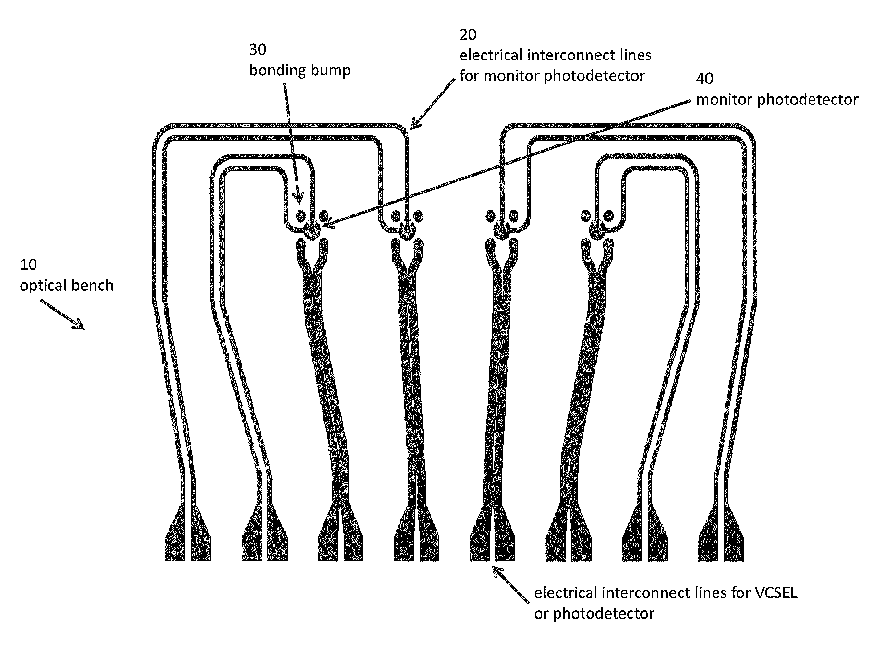
[0075]In an embodiment of the invention, an optical bench apparatus may have a transparent substrate with electrical interconnect lines and / or pads for attaching transmitters and / or receivers by flip-chip bonding. Aligned to these bonding sites may be monitor photodetectors that may be designed to absorb a small fraction of the transmitted and / or received light and convert it into a monitor photocurrent for optimizing bias and / or modulation currents to achieve desired operating characteristics of the transmitter and / or an optical link.

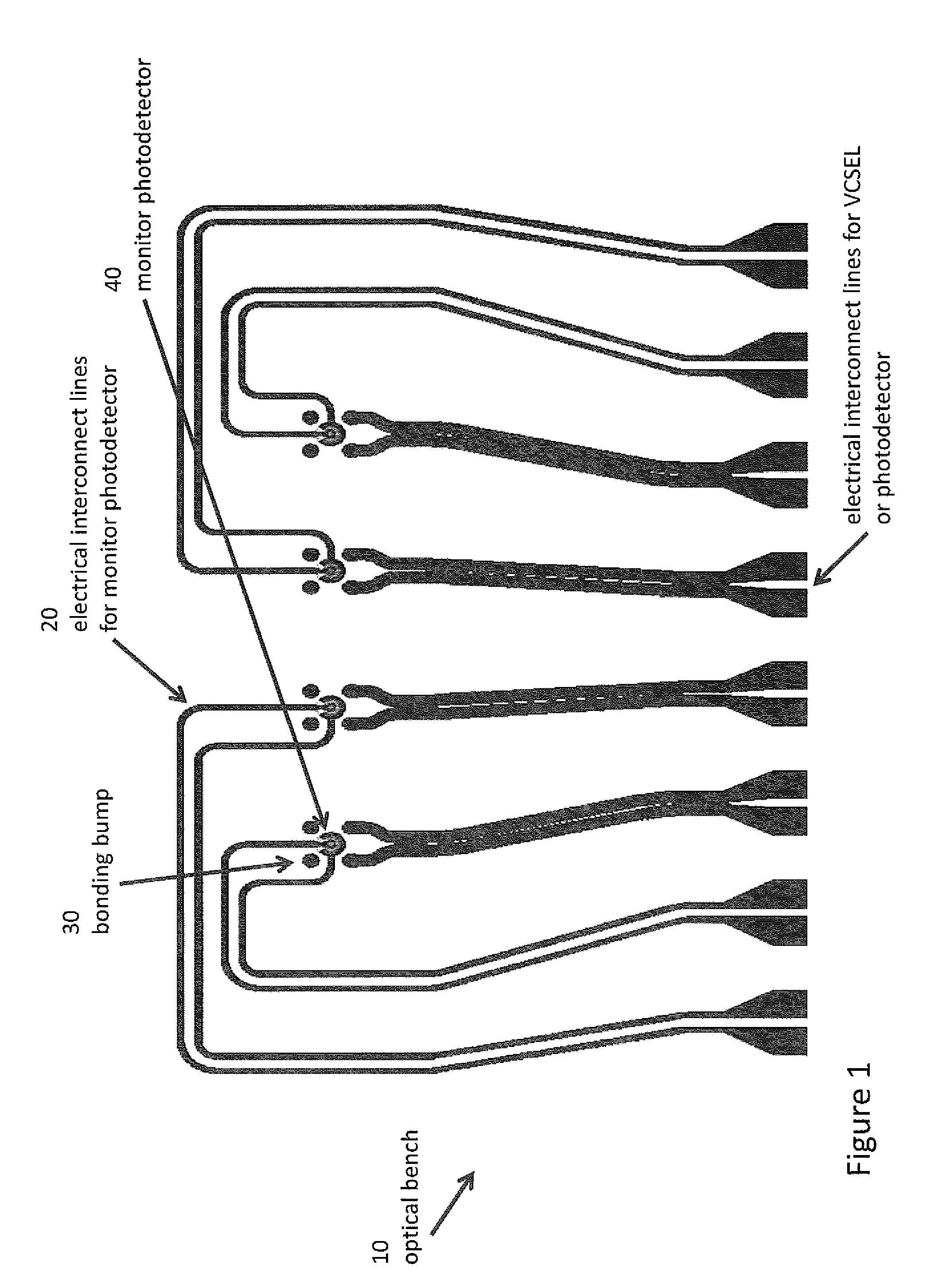
[0076]Referring now to the Figures where like numerals indicate like elements, a schematic diagram of an embodiment of the optical bench apparatus is shown in FIG. 1. In particular, FIG. 1 schematically illustrates an optical bench apparatus 10 having a transparent substrate with electrical interconnect lines 20 for monitor photodetectors and / or bonding sites 30 for attaching transmitters (see FIGS. 2 and 3) and / or receivers (see FIGS. 2 and 3) by flip...


PUM

PropertyMeasurementUnit
transparentaaaaaaaaaa
optical outputaaaaaaaaaa
impedanceaaaaaaaaaa

Abstract

Optical bench structure provides a platform for integrating optical transmitters, particularly Vertical-Cavity Surface-Emitting Lasers (VCSELs), with monitor photodetectors. A substrate with photodetectors on the front side is aligned with flip-chip bonding bumps so the emission of the transmitters is aligned with the monitor photodetectors and passes through the monitor photodetectors with a portion of the transmitted light absorbed by the monitor photodetectors. The photodetectors have a thin absorption region so the percentage of light absorbed may be relatively small, providing sufficient photocurrent to monitor the transmitted power having a minimal effect on the transmitted power. Microlenses are integrated on the backside of the substrate focus, steer and/or collimate the emitted optical beams from the transmitters. The structure enables photodetectors to be integrated on the optical bench allowing the received optical power to be monitored. The receiver photodetectors are integrated on the optical bench alone and/or in combination with the transmitters.

Description

CROSS REFERENCE TO RELATED APPLICATIONS[0001]This application claims the benefit of U.S. Provisional Application Ser. No. 61 / 747,415 entitled “Optical Bench Apparatus and Method” filed Dec. 31, 2012 which is hereby incorporated herein by reference in its entirety.BACKGROUND OF THE INVENTION[0002]This invention relates generally to optical power monitoring. In particular, the invention relates specifically to an optical bench apparatus having integrated monitor photodetectors and a method for monitoring optical power using the optical bench apparatus for optical power monitoring in optical modules. Monitoring the level of optical power emitted by transmitters may be a highly desirable feature in many optical modules, especially optical transceivers. Monitoring the optical power may allow the bias and / or modulation currents to be optimized to achieve the desired operating characteristics of both the transmitter itself, as well as the entire optical link. Such optimization of the bias ...

Claims


Application Information

Patent Timeline
Patent Type & Authority Applications(United States)
IPC IPC(8): H04B10/50H04B10/079
CPCH04B10/07955H04B10/501H04B10/0799H04B10/40H04B10/5057G01J1/4257G02B1/11G02B6/4286
Inventor LOUDERBACK, DUANE
Owner ZEPHYR PHOTONICS
Why Eureka
Try Eureka