Granulation process and apparatus

a technology of granulation process and apparatus, which is applied in the direction of granulation using vibration, dough shaping, manufacturing tools, etc., can solve the problems of difficult obtention of good monodispersion, and achieve better monodispersion, high production rate, and better final product quality

Active Publication Date: 2012-05-29
CASALE SA
View PDF6 Cites 0 Cited by
  • Summary
  • Abstract
  • Description
  • Claims
  • Application Information

AI Technical Summary

Benefits of technology

[0023]In further (not shown) embodiments, the perforated side wall may be mechanically disconnected from the frame part of the bucket, preferably with suitable means (gasket or equivalent) to avoid fluid leakage.
[0026]This good monodispersion of the droplets at high rpm leads to a more valuable final product combined with a high production rate.
[0027]Further to the advantages of a better monodispersion and better quality of the final product, the invention provides that the mass to be put into vibration is reduced compared to present vibrating buckets, being equal to the mass of the perforated side wall and of a small quantity of liquid.
[0028]There are a number of advantageous effects related to the lower vibrating mass. First, the vibrational forces on the supports and risk of mechanical failure are greatly reduced in comparison with the prior art. The above cited known solution of U.S. Pat. No. 4,585,167, for example, suffers severe stress of the driving shaft, subjected to both torsional and vibrating forces. Secondly, a reduced vibrating mass allows the use of a smaller and faster vibrating engine compared to a prior-art apparatus. It should be noted that available vibrating engines capable of generate high forces are commonly limited to a relatively low frequency of operation, while vibrating engines capable of high frequencies can produce a limited force, being unsuitable for vibrating a considerable mass. The invention allows to overcome this limitation, for example applying high frequency vibrations to a large prilling bucket rotating at high speed. Energy consumption is also reduced.

Problems solved by technology

A major challenge of the granulation process is to produce a monodispersed flow, i.e. a flow of liquid droplets having (as much as possible) the same shape, preferably spherical, and the same size.
However, there is a continuous need of improving the monodispersion of droplets, especially at high rotational speed when a monodispersed flow is more difficult to achieve.
In particular, the obtention of a good monodispersion is more difficult at speeds higher than 50-80 rpm (revolutions per minute).

Method used


Image

  • Granulation process and apparatus
  • Granulation process and apparatus
  • Granulation process and apparatus

Examples


Embodiment Construction

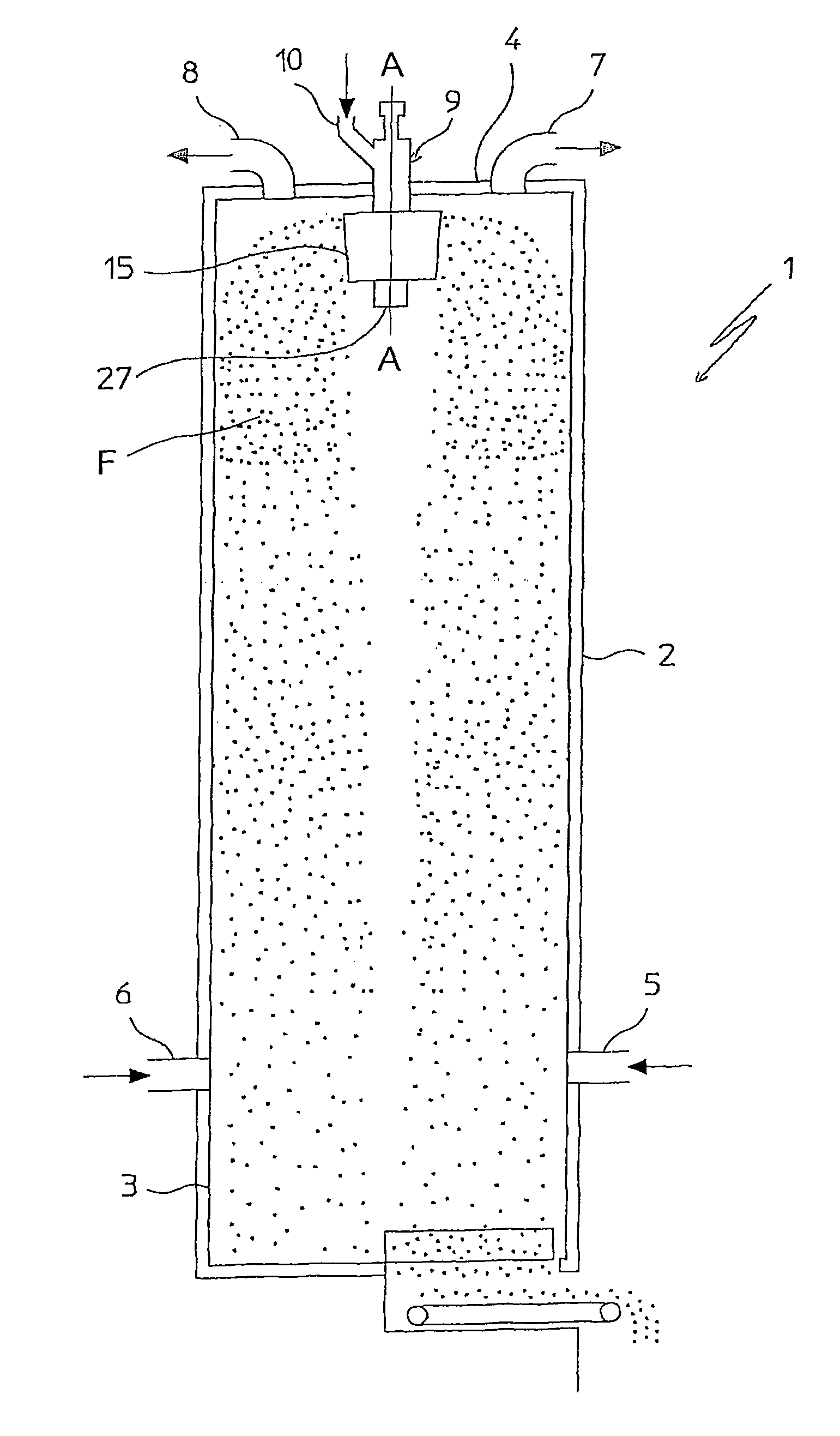
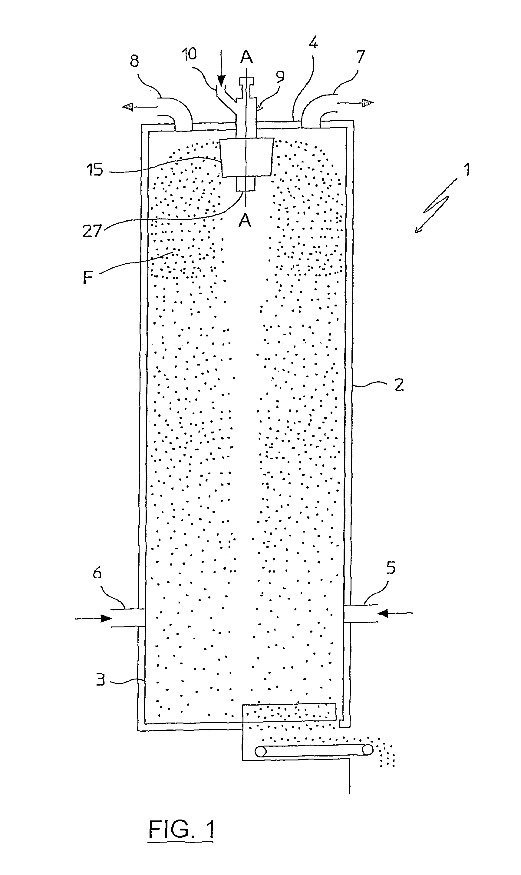
[0032]With reference to FIG. 1, an apparatus for the granulation of a liquid substance, for example urea, is shown, comprising a prilling tower 1 equipped with a prilling bucket 15. The prilling bucket 15 is located inside the tower 1 and near the top thereof.

[0033]The prilling tower 1 has a cylindrical shell 2 with a vertical axis A-A, and is closed at the opposite ends by a base plate 3 and a top wall or panel 4. Ducts 5 and 6 are provided, at the base of the shell 2, to produce a continuous rising flow of a suitable cooling gaseous medium, e.g. cooling air, into the tower 1. Further ducts 7, 8 are provided on top panel 4 to discharge the cooling medium and possibly a vapour fraction extracted from the substance to be granulated.

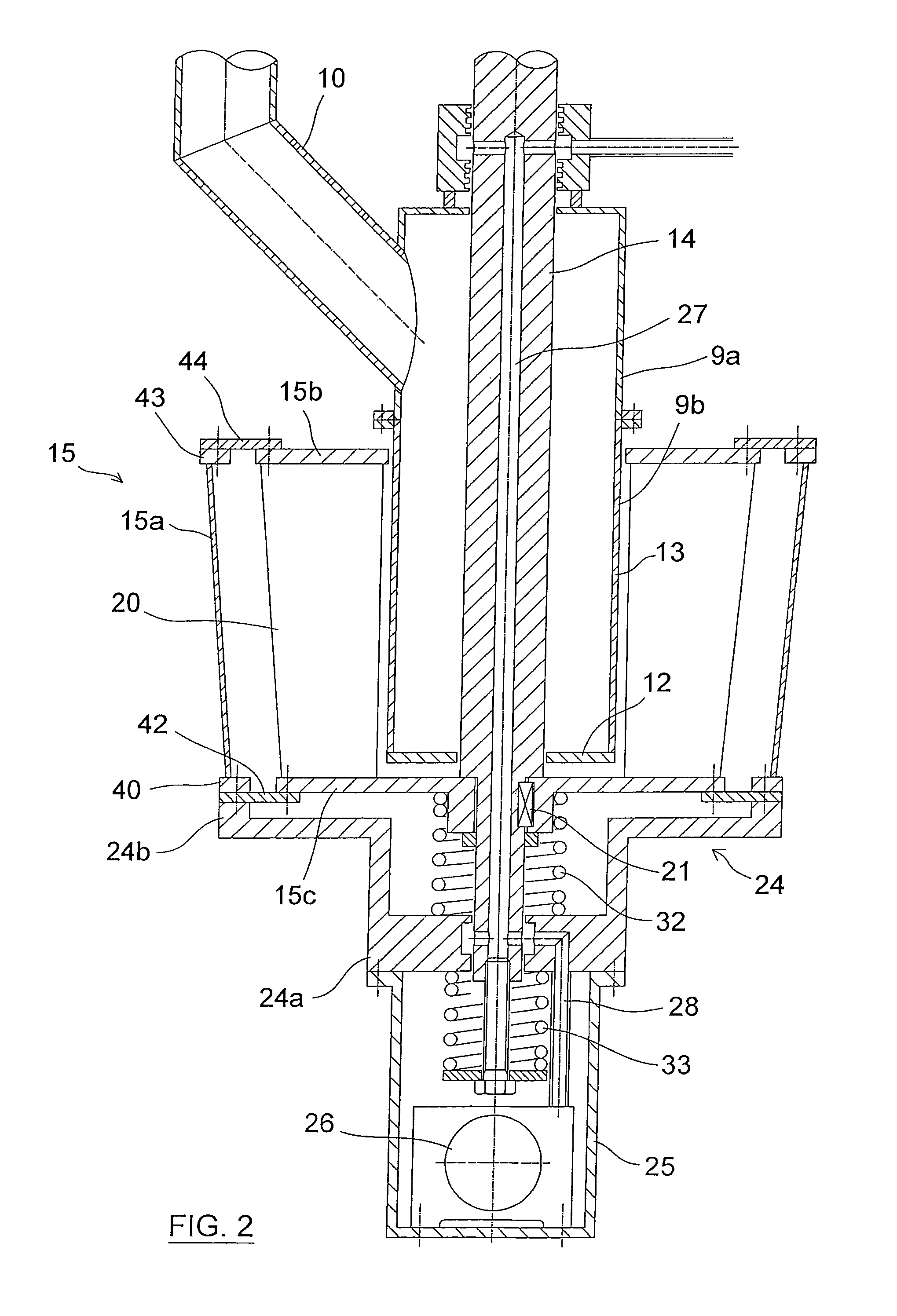
[0034]The top wall 4 is crossed centrally by a tubular cylindrical hopper or duct 9, for feeding the liquid substance to be granulated. More in detail, the duct 9 has a portion 9a outside the shell 2 connected to a feeding duct 10 of the liquid substance, ...


PUM

PropertyMeasurementUnit
massaaaaaaaaaa
flexibleaaaaaaaaaa
thicknessaaaaaaaaaa

Abstract

A granulation process wherein a liquid is sprayed into a prilling tower (1) by means of a rotating prilling bucket (15) having a perforated side wall (15a), and the liquid jets exiting said perforated side wall are subjected to a vibrating action according to the axial direction (A-A) of the prilling tower (1), while the remaining liquid mass inside the bucket is kept substantially free from said vibrating action. A suitable apparatus is also disclosed, wherein the peripheral side wall (15a) of the prilling bucket (15) is connected to vibration imparting means and has a flexible connection with the frame (15b, 15c) of the bucket.

Description

FIELD OF APPLICATION[0001]The present invention relates, in its most general aspect, to the granulation of a fluid or semi-fluid substance.[0002]In particular, the invention relates to a granulation process wherein a fluid substance is fed to a rotating prilling bucket located inside a prilling tower, containing a given liquid mass of said substance and having a perforated side wall, and said fluid substance is sprayed from said prilling bucket into the prilling tower in the form of liquid jets through said perforated side wall. The invention also relates to an apparatus adapted to carry out the above method. A preferred application of the invention is the production of granules or prills of urea.PRIOR ART[0003]The granulation of a given substance available in a fluid state (e.g. dispersed or dissolved in a liquid phase, or even in melted state) is performed in a cylindrical tower, also known as prilling tower, wherein a downward flow of small droplets of said substance is produced,...

Claims


Application Information

Patent Timeline
Patent Type & Authority Patents(United States)
IPC IPC(8): B29B9/00
CPCB01J2/04B05B3/1021B05B3/001B01J2/18
Inventor RIZZI, ENRICO
Owner CASALE SA
Why Eureka
Try Eureka