Self-positioning device for water turbine

Active Publication Date: 2014-07-03
KUN SHAN UNIVERSITY
View PDF4 Cites 5 Cited by
  • Summary
  • Abstract
  • Description
  • Claims
  • Application Information

AI Technical Summary

Benefits of technology

The present invention is a self-positioning device for a water generator that can be used at different depths in the ocean without spinning about either the Y or X axis. It uses a balance wing and side wings to keep it stable and avoid spinning, as well as a lifting wing to position it at a desired depth and ensure consistent and effective functioning. The device can be easily installed and retrieval, reducing maintenance costs and protecting the water generator.

Problems solved by technology

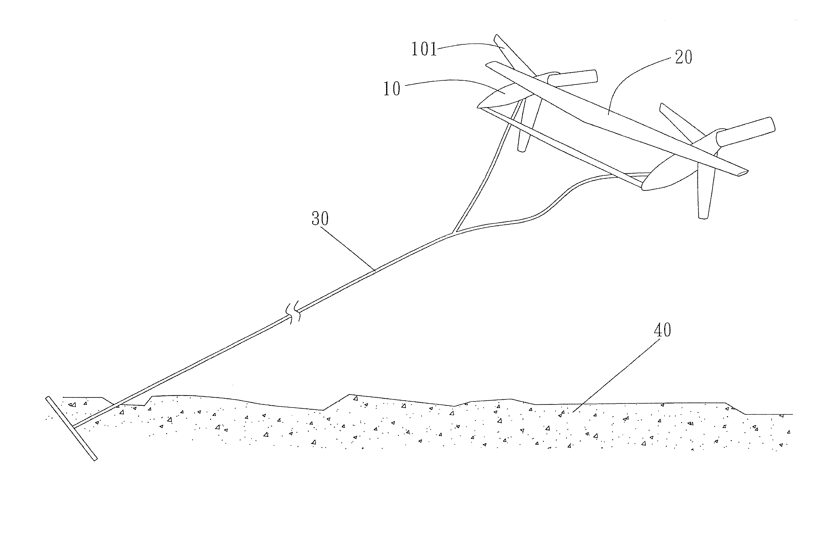
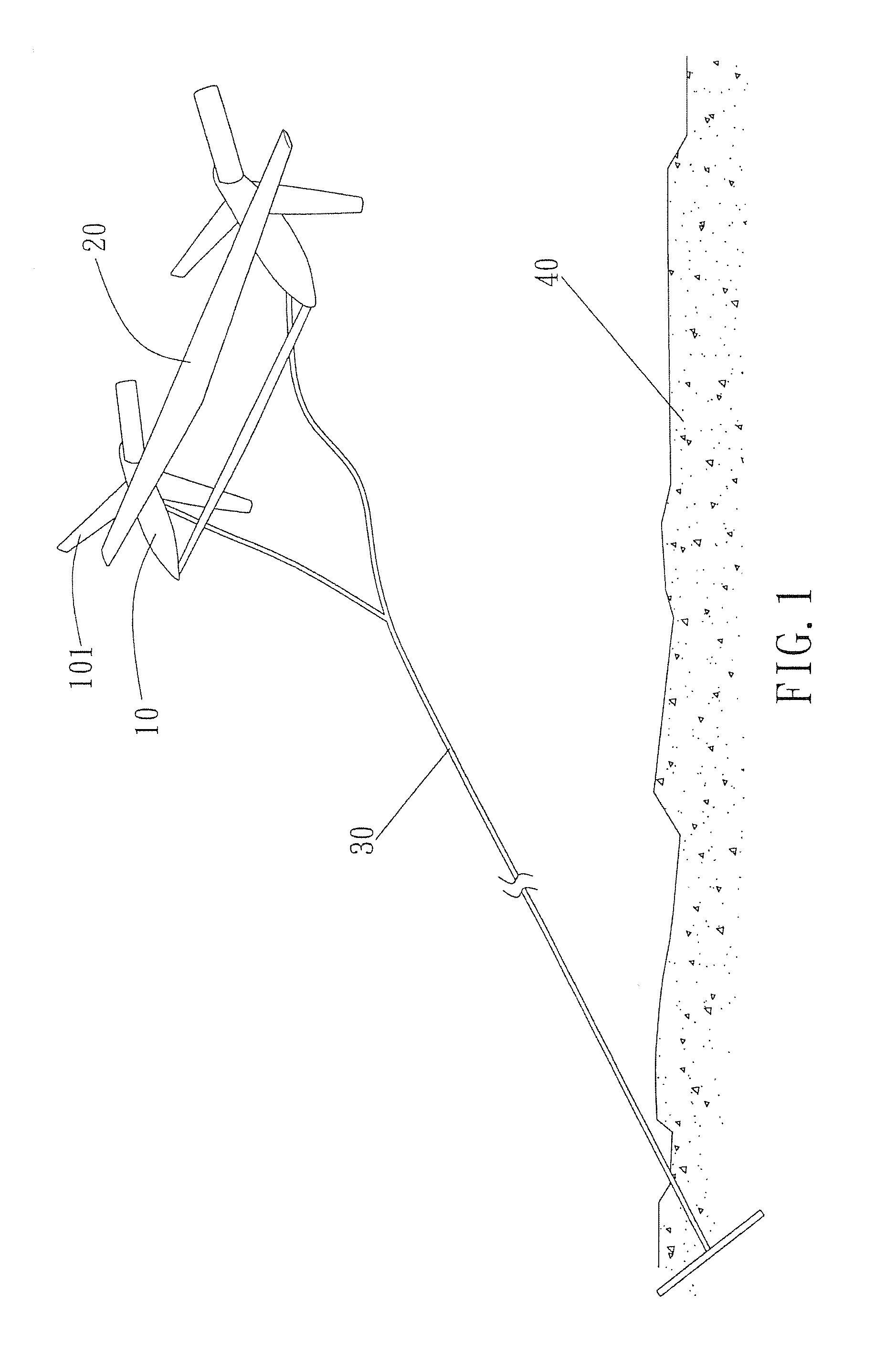
Therefore, the conventional generators can only be set close to the land and the current speed is too slow to effectively drive the generators 10.
The depth of the ocean at the east cost of Taiwan is about 1000 to 4000 meters, and it is difficult to fix the cable 30 on the sea bad 40.
The maintenance will be difficult when the climate conditions become bad.
Typhoons can easily damage the generators 10 and the blades 101 are difficult to face the currents because the currents have different directions so that the efficiency of the generators 10 is low.
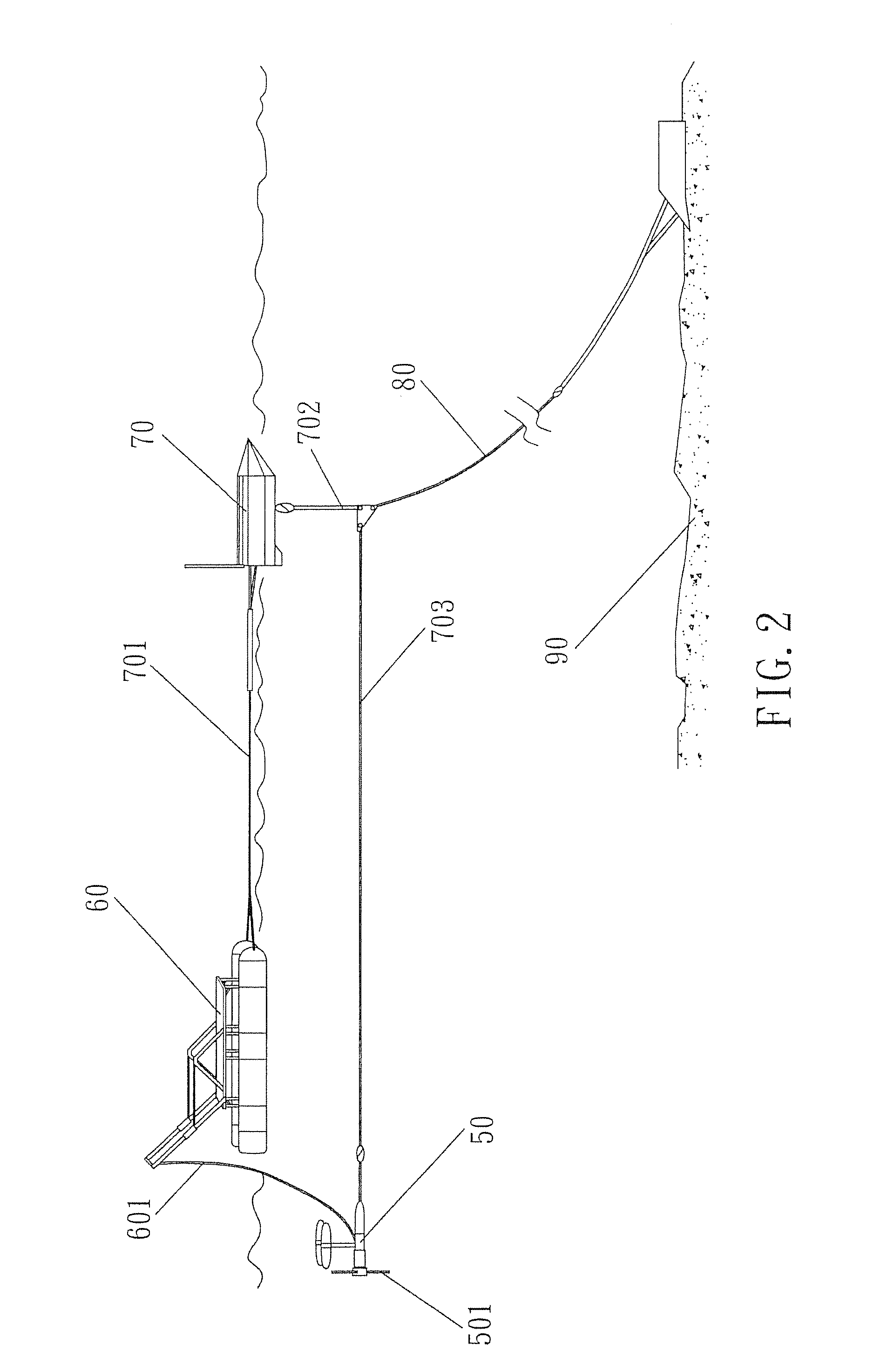
The sea bad 90 at the deep ocean makes the installation and maintenance be a huge task.
The bad climate can easily damage the turbine generator 50 and the change of the current affects the efficiency of the turbine generator.

Method used


Image

  • Self-positioning device for water turbine
  • Self-positioning device for water turbine
  • Self-positioning device for water turbine

Examples


Embodiment Construction

[0024]Referring to FIGS. 3 to 7, the water generator assembly of the present invention comprises a water generator 1 having two forwarding wings 11 on the front end thereof and the forwarding wings 11 are located on the X-axis of the water generator 1. The forwarding wings 11 are designed by the principles of sailing against current, the forwarding wings 11 are applied by the current and generating a resistance force FD and a lifting force FL, the resistance force FD and the lifting force FL are combined as a composition force FC which has a forwarding component force FF in the X-axis so as to offset the drag force cause by the current applying to the water generator 1, and a side component force FS in Y-axis of the water generator 1 is offset by the forwarding wings 11.

[0025]The water generator 1 has a balance wing 12 which prevents the water generator 1 from spinning about the X-axis.

[0026]The water generator 1 has a lifting wing 13 which generates a lifting force to lift the wate...


PUM


Abstract

A water generator assembly includes a water generator having two forwarding wings on the front end thereof and the forwarding wings are applied by current and generate a resistance force and a lifting force. The resistance force and the lifting force are combined as a composition force which has a forwarding component force in the X-axis to offset the drag force cause by the current applying to the water generator. A component force in Y-axis is offset by the forwarding wings. A balance wing is connected to the water generator to prevent the water generator from spinning about the X-axis. The water generator has a lifting wing to generate a lifting force to lift the water generator. A buoyant floats and indexes the water generator. A tail wing and two side wings keep the water generator facing the current and prevent the water generator from spinning about the Y-axis.

Description

FIELD OF THE INVENTION[0001]The present invention relates to a self-positioning device, and more particularly, to a self-positioning for positioning the water turbine in the open ocean without using tower stands on the sea bed.BACKGROUND OF THE INVENTION[0002]The conventional ocean has potential hydrokinetic energy because the current of the ocean has stable speed and direction. For example, the Kuroshio current flows toward north consistently and the speed is about 1 m / s at the distance about 1 km from Taiwan, and the width is about 150 km. If a two-blade turbine ocean current generator of 1 MW is set offshore from the island of Lyudao about 3 kin, there is an area about 25 square km where the Kuroshio current has the highest current speed. The two-blade turbine ocean current generator is estimated to generate energy of 1GW to 3GW, and which is equal to the designated amount of power of three nuclear power plants. Furthermore, ocean current generator is more environmentally-friendl...

Claims


Application Information

Patent Timeline
IPC IPC(8): F01D7/00
CPCF05B2240/97F01D7/00F03B17/061Y02E10/28Y02E10/30Y02E10/20
Inventor LIN, SHUEEI-MUH
Owner KUN SHAN UNIVERSITY
Why Eureka
Try Eureka