
Dual fuel nozzle tip assembly

a dual-fuel combustor and fuel nozzle technology, which is applied in the direction of hot gas positive displacement engine plants, combustion processes, lighting and heating apparatus, etc., can solve the problems of damage to the center body tip, high thermal stress at the central body, and formation of coking

Active Publication Date: 2014-07-10
GENERAL ELECTRIC CO
View PDF3 Cites 51 Cited by
  • Summary
  • Abstract
  • Description
  • Claims
  • Application Information

AI Technical Summary

Benefits of technology

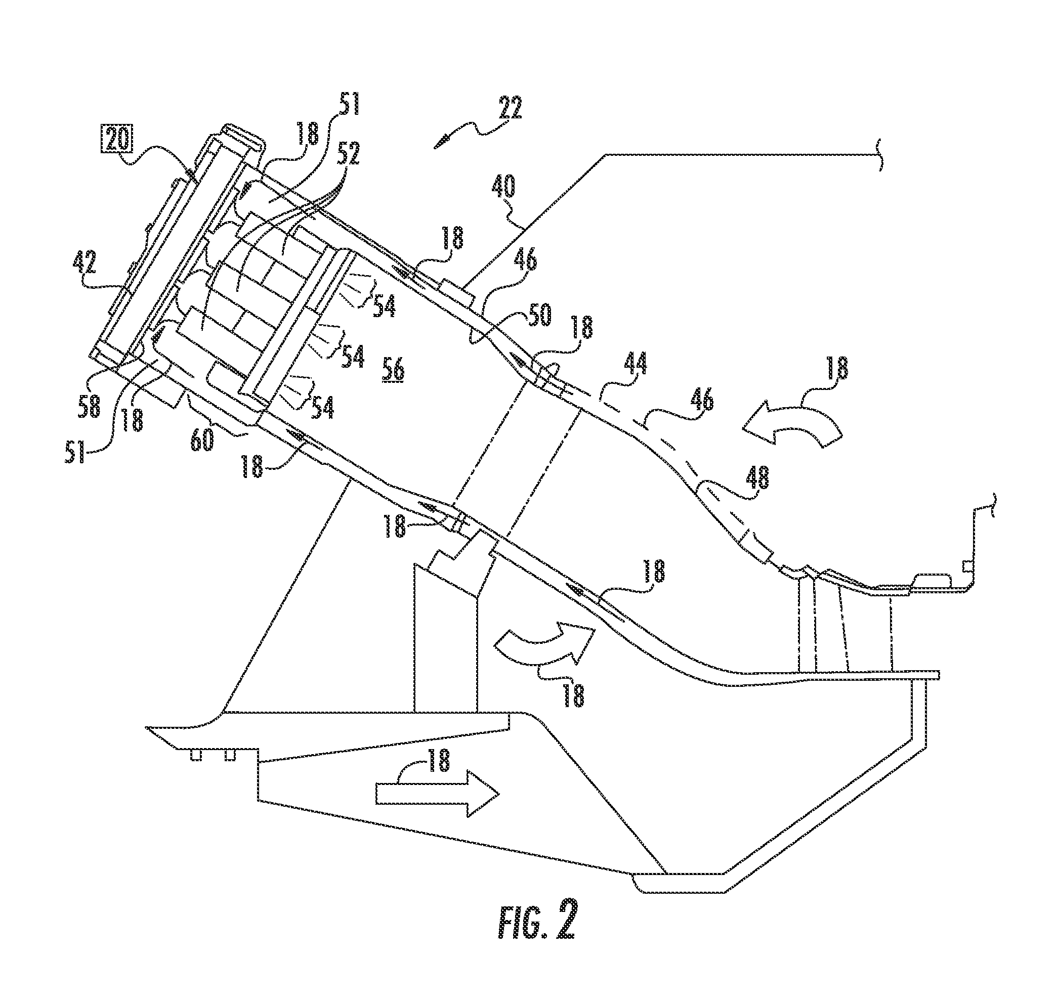
The present invention is a fuel nozzle for a gas turbine that includes a burner tube component and a center nozzle assembly concentrically disposed within the burner tube component. The center nozzle assembly has an annular center body that at least partially defines a cooling air flow passage through the center nozzle assembly. The center body also includes a downstream end. A premix flow passage is defined between the burner tube component and the center body. A central recirculation zone for premix flame stabilization is defined in the area of combustion zone downstream from the center body. A tip assembly is disposed at the downstream end of the center body, including an impingement plate and a radially extending cap that at least partially define a cooling plenum therebetween. A plurality of cooling ports extends through the impingement plate to provide for fluid communication between the cooling air flow passage and the cooling plenum. The invention also includes a gas turbine having a combustor with a fuel nozzle and a tip assembly.

Problems solved by technology

Where a liquid fuel is used for diffusion mode operation, coking forms and high thermal stresses occur at a central body tip portion of the fuel nozzle.
However, because of the proximity of the LFC tip with respect to the combustion zone of the combustor, heat from the combustion gases and / or heat due to heating during premix mode operation may damage the center body tip over time.
In addition, in certain configurations where the fuel nozzle is configured to flow both the gas fuel and the liquid fuel, the liquid fuel causes coke deposit formation or coking on a heated downstream surfaces of the center body tip.
However, despite the general effectiveness of this system and / or method for cooling the nozzle tip, center body tips are still a life limiting component of this type of fuel nozzle.

Method used


Image

  • Dual fuel nozzle tip assembly
  • Dual fuel nozzle tip assembly
  • Dual fuel nozzle tip assembly

Examples


Embodiment Construction

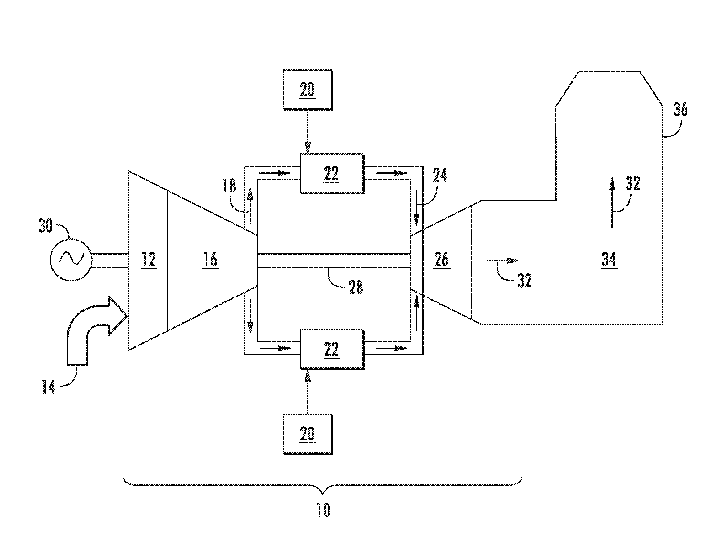
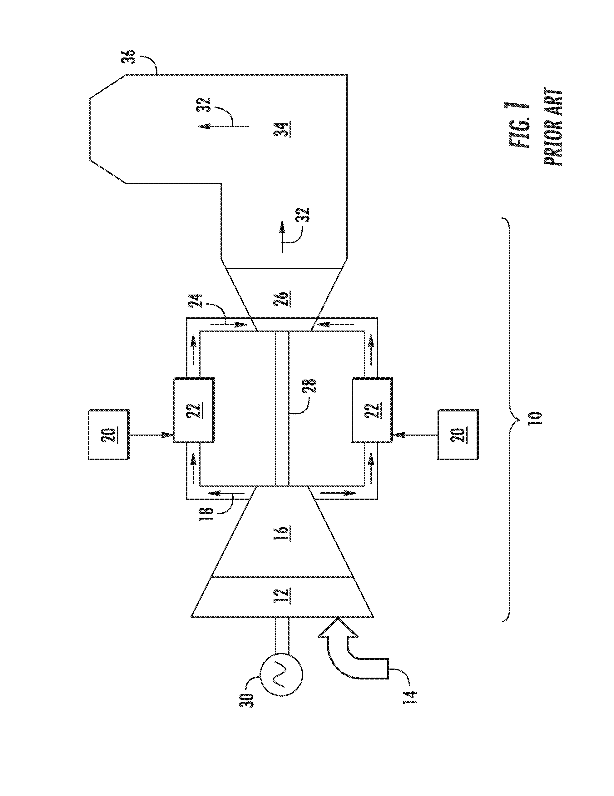
[0021]Reference will now be made in detail to present embodiments of the invention, one or more examples of which are illustrated in the accompanying drawings. The detailed description uses numerical and letter designations to refer to features in the drawings. Like or similar designations in the drawings and description have been used to refer to like or similar parts of the invention. As used herein, the terms “first”, “second”, and “third” may be used interchangeably to distinguish one component from another and are not intended to signify location or importance of the individual components. The terms “upstream,”“downstream,”“radially,” and “axially” refer to the relative direction with respect to fluid flow in a fluid pathway. For example, “upstream” refers to the direction from which the fluid flows, and “downstream” refers to the direction to which the fluid flows. Similarly, “radially” refers to the relative direction substantially perpendicular to the fluid flow, and “axiall...


PUM


Abstract

A fuel nozzle for a combustor includes a burner tube and a center nozzle assembly disposed within the burner tube. The center nozzle assembly includes a center body that at least partially defines a cooling air flow passage through the center nozzle assembly. A premix flow passage is defined between the burner tube and the center nozzle assembly. A tip assembly is disposed at a downstream end of the center body. The tip assembly includes an impingement plate, and a cap that is disposed downstream from the impingement plate. The impingement plate and the cap at least partially define a cooling plenum therebetween. An insert passage extends through the impingement plate and a cooling flow outlet extends through the cap. A plurality of cooling ports extends through the impingement plate to provide for fluid communication between the cooling air flow passage and the cooling plenum.

Description

FIELD OF THE INVENTION[0001]The present invention generally involves a fuel nozzle for a combustor. More specifically, the invention relates to a center body tip assembly for a dual-fuel fuel nozzle for a combustor of a gas turbine.BACKGROUND OF THE INVENTION[0002]In a gas turbine, fuel nozzles are used to mix a compressed working fluid such as air with a fuel for combustion within a combustion zone that is positioned downstream from the fuel nozzles. Some fuel nozzles are configured to operate on one type of fuel such as a gas fuel during gas fuel operation mode and on a second type of fuel such as a liquid fuel during liquid fuel operation mode. Where a liquid fuel is used for diffusion mode operation, coking forms and high thermal stresses occur at a central body tip portion of the fuel nozzle.[0003]A particular fuel nozzle configuration that is capable of both gas and liquid mode operation generally includes an outer premix flow passage that is at least partially defined by a bu...

Claims


Application Information

Patent Timeline
IPC IPC(8): F23R3/28F23R3/14
CPCF23R3/14F23R3/283F23R3/286F23R3/36F23R2900/03044
Inventor SHERSHNYOV, BORYS BORYSOVYCHGINESSIN, LEONID YULYEVICH
Owner GENERAL ELECTRIC CO
Learn More