Light-emitting arrangement

a technology of light-emitting arrangement and phosphor, which is applied in the direction of light source combination, lighting and heating apparatus, semiconductor devices of light sources, etc., can solve the problems of unappealing in many applications, phosphor yag:ce has a distinct yellowish appearance, and the color of phosphor may be clearly visible, so as to increase the amount of light converted, the effect of improving the system and increasing the path length of light within the wavelength converting domain

Inactive Publication Date: 2014-07-10
SIGNIFY HLDG BV +1
View PDF6 Cites 2 Cited by
  • Summary
  • Abstract
  • Description
  • Claims
  • Application Information

AI Technical Summary

Benefits of technology

[0023]Typically, the primary wavelength converting domain and / or the secondary wavelength converting domain comprises, in addition to the respective wavelength converting material, non-converting scattering particles. By including scattering materials in the wavelength converting domain the path length of the light within the wavelength converting domain may be increased, thus increasing the amount of light converted. Alternatively, a lower amount of wavelength converting material may be used to achieve an acceptable result.
[0024]In embodiments of the invention, the primary wavelength converting domain and the optical element, and / or the optical element and the secondary wavelength converting domain, are in direct optical contact. When the diffuser is in direct optical contact with either or both of the wavelength converting domains the efficacy of the system is improved, but without resulting in unacceptably high visibility of the primary wavelength converting domain. When the optical element is not in direct optical contact with the secondary wavelength converting domain. more ambient light is absorbed and reflected by the secondary wavelength converting domain.

Problems solved by technology

A disadvantage of current LED-phosphor based illumination devices is that in the functional off-state of the device, the color of the phosphor may be clearly visible.
For example, the commonly used phosphor YAG:Ce has a distinct yellowish appearance, which may be unappealing in many applications.

Method used


Image

  • Light-emitting arrangement
  • Light-emitting arrangement
  • Light-emitting arrangement

Examples


example 1

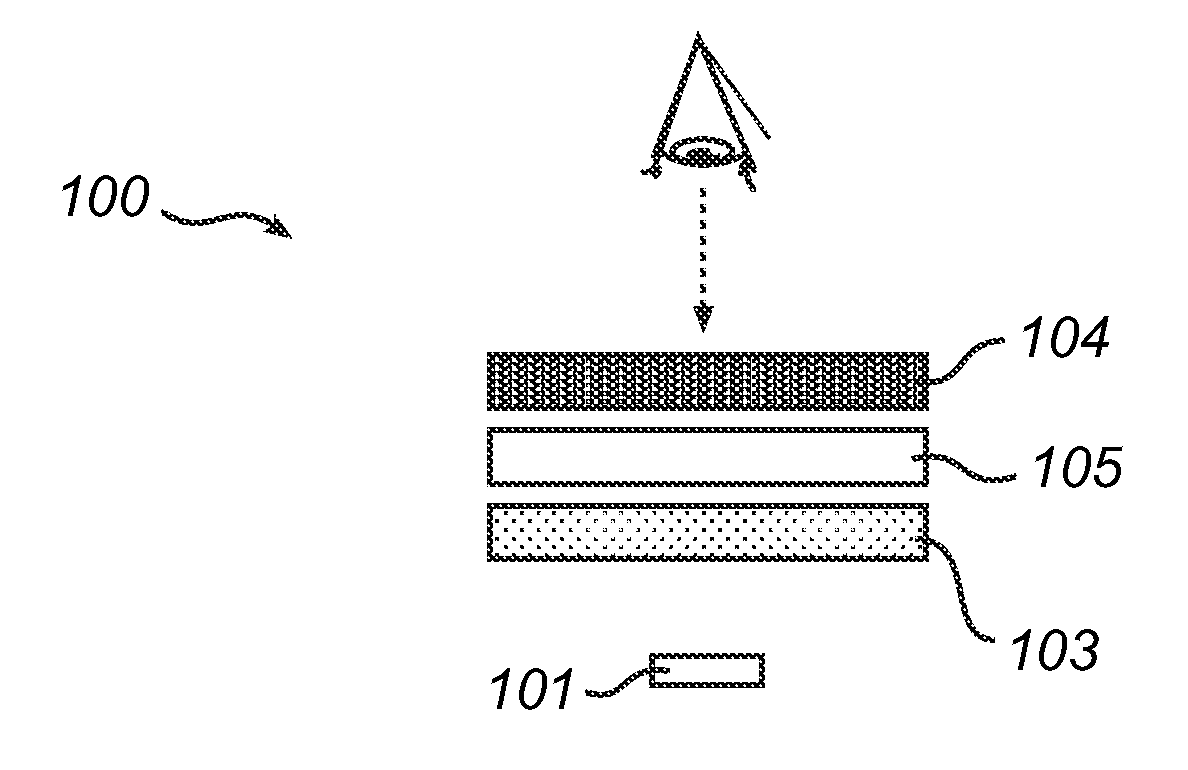
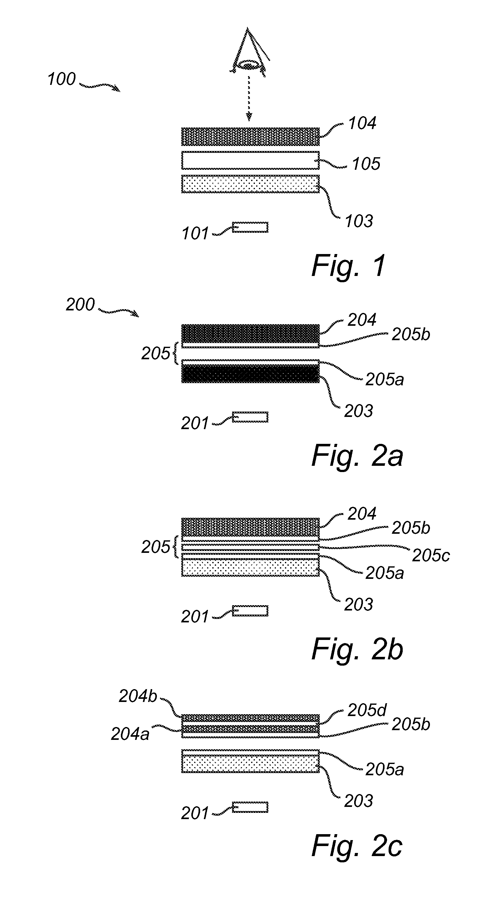
[0075]In one example, the light emitting arrangement comprises a stack of: a blue LED light source having an emission peak wavelength (PWL) of 455 nm, a primary wavelength converting domain comprising BSSN in PMMA, a diffuser in the form of TiO2 particles dispersed in PMMA; and a secondary wavelength converting domain comprising LuAG.

example 2

[0076]In another example, the light emitting arrangement comprises a stack of: a blue LED light source having an emission a peak wavelength (PWL) of 450 nm, a primary wavelength converting domain comprising Lumogen® Red F305 (BASF) in PMMA; a diffuser in the form of TiO2 particles dispersed in PMMA, and a secondary wavelength converting domain comprising LuAG.

example 3

[0077]In another example, the light emitting arrangement comprises a stack of: a blue LED light source having an emission peak wavelength (PWL) of 445 nm, a primary wavelength converting domain comprising Lumogen® Red F305 and Lumogen® Orange F240 (BASF) in PMMA a diffuser in the form of TiO2 particles dispersed in PMMA, and a secondary wavelength converting domain comprising Lumogen® F083 (BASF).


PUM


Abstract

A light emitting arrangement is provided, comprising:—a light source capable of emitting light of a first wavelength range;—a primary wavelength converting domain arranged to receive light emitted by said light source and capable of converting at least part of the light of said first wavelength range into light of a second wavelength range;—a secondary wavelength converting domain arranged to receive ambient light and capable of converting light into light of a third wavelength range from 470 nm to less than 570 nm, wherein said primary wavelength converting domain is arranged between said light source and said secondary wavelength converting domain; and—an optical element arranged in the path of light between said primary and secondary wavelength converting domains. By using the suggested arrangement a desirable off-state green or greenish appearance is obtained, using minor amounts of phosphor and with high light extraction efficiency.

Description

FIELD OF THE INVENTION[0001]The invention relates to a light-emitting arrangement comprising wavelength converting domains.BACKGROUND OF THE INVENTION[0002]Semiconductor-based based illumination devices are increasingly used for a wide variety of lighting applications, including general and decorative lighting applications. For example, light-emitting diodes (LEDs) offer advantages over traditional light sources, such as incandescent and fluorescent lamps, including long lifetime, high lumen efficacy, low operating voltage and fast modulation of lumen output.[0003]Efficient high-power LEDs are often based on blue light emitting materials. To produce an LED based illumination device having a desired color (e.g., white) output, a suitable wavelength converting material, commonly known as a phosphor, may be used which converts part of the light emitted by the LED into light of longer wavelengths so as to produce white light. For instance, the light source may comprise a blue LED with o...

Claims


Application Information

Patent Timeline
Patent Type & Authority Applications(United States)
IPC IPC(8): H01L33/50
CPCH01L33/507H01L33/505F21Y2113/13F21Y2115/10F21V9/38H01L33/44H01L33/504H01L33/50
Inventor VAN BOMMEL, TIESHIKMET, RIFAT ATA MUSTAFA
Owner SIGNIFY HLDG BV
Why Eureka
Try Eureka