

Electro-mechanical energy harvesting switch
a technology of electrical energy harvesting switch and electromechanical technology, applied in the direction of switch power arrangement, contact mechanism, relay, etc., can solve the problems of complex mechanism, limited life of battery, risk of failure or replacement, etc., and achieve the effect of cost-effective production
- Summary
- Abstract
- Description
- Claims
- Application Information
AI Technical Summary
Benefits of technology
Problems solved by technology
Method used
Image

Examples
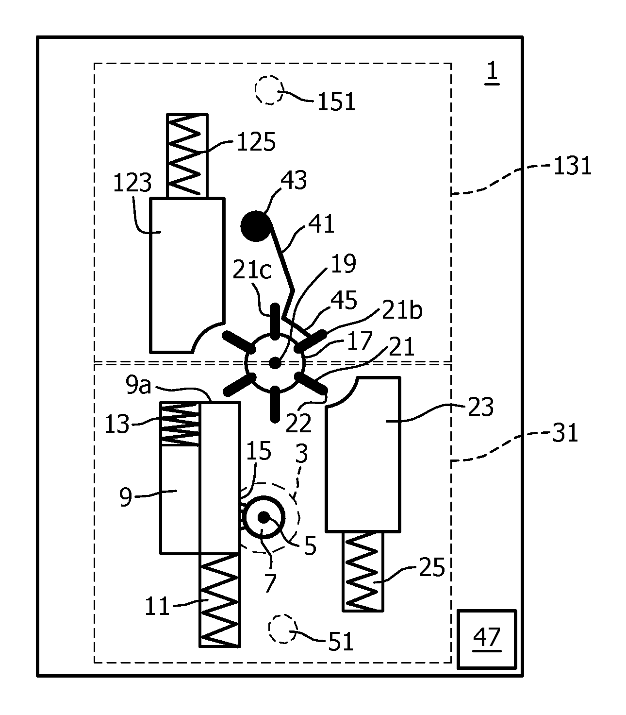
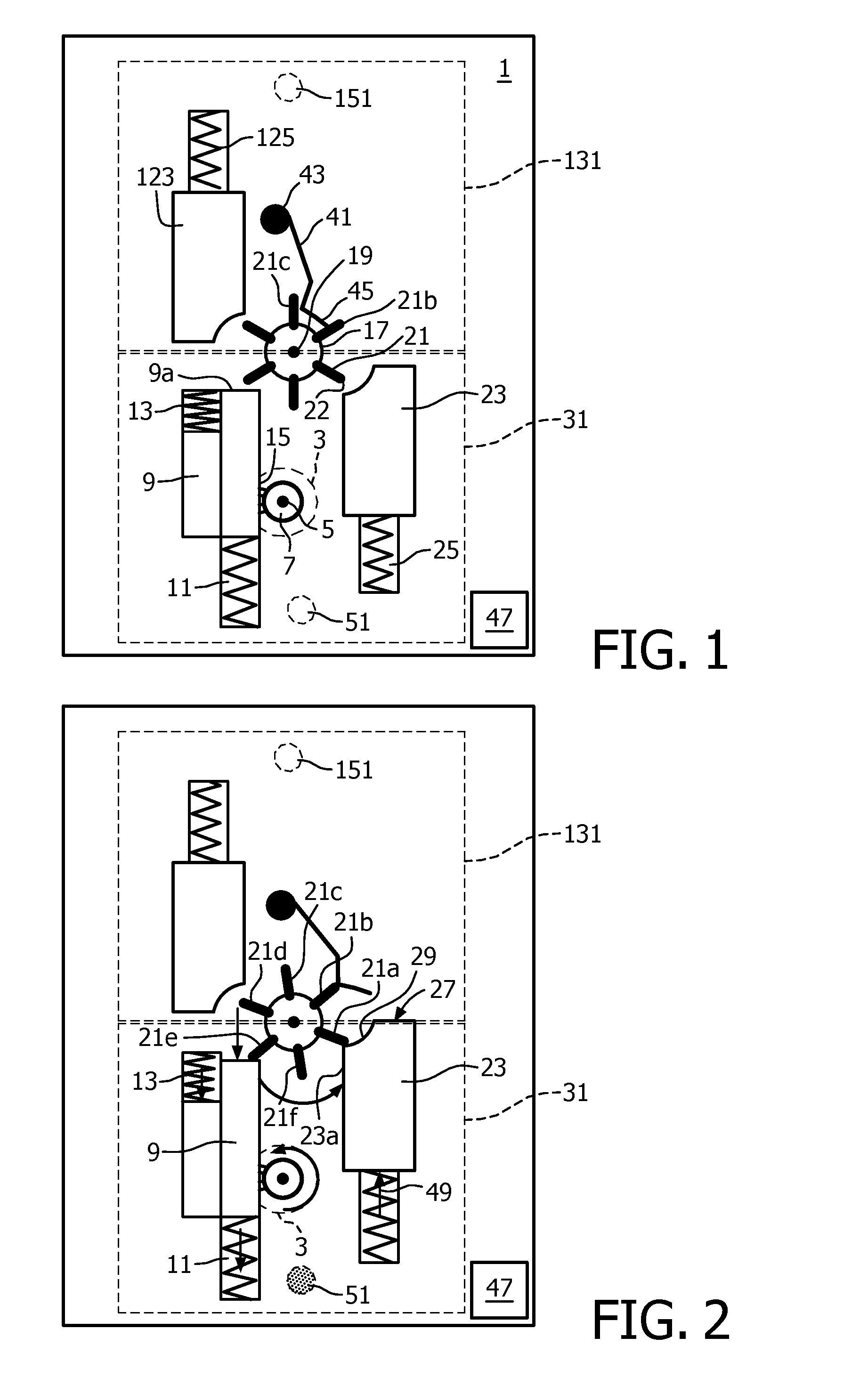
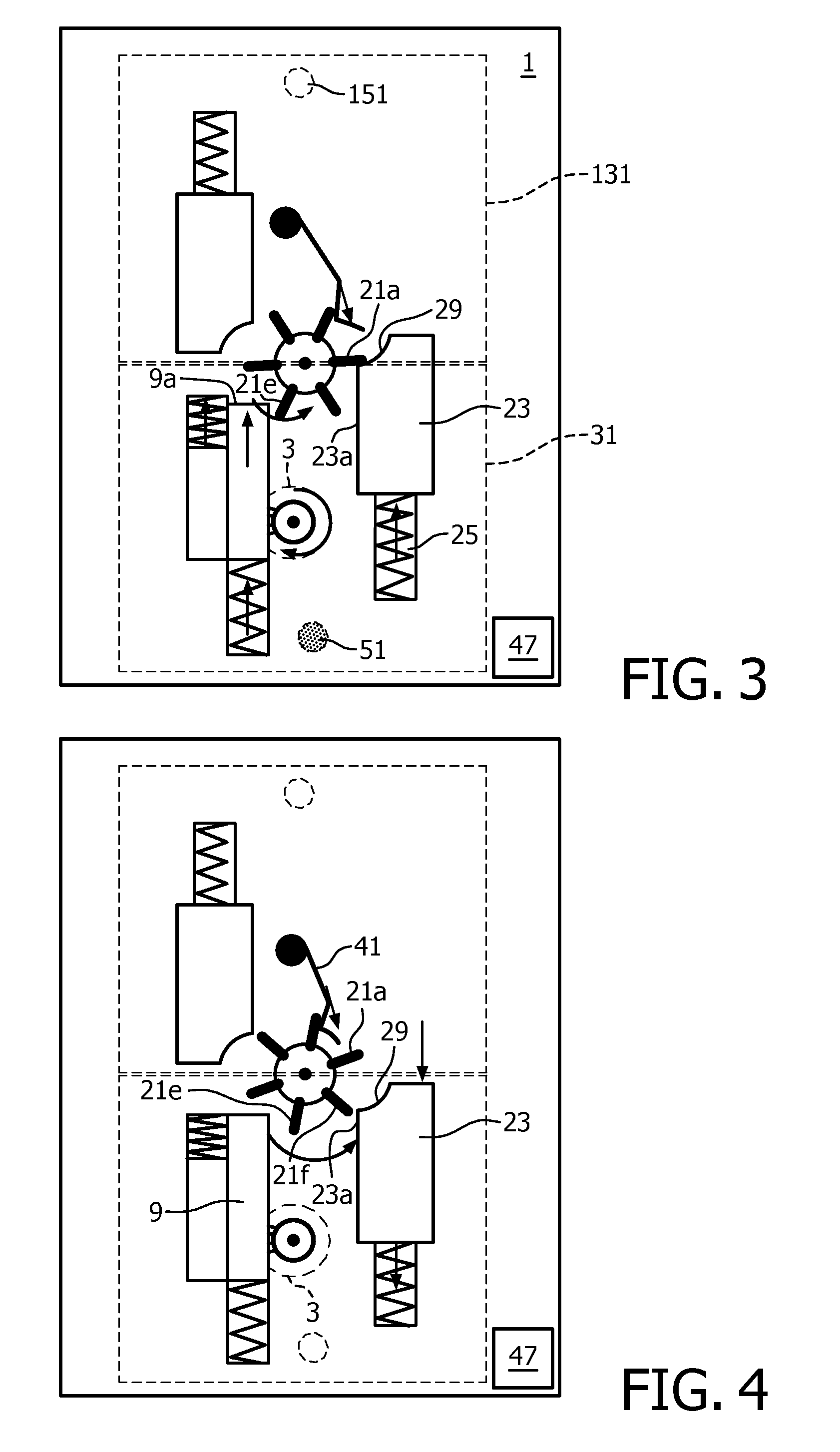
first embodiment
[0069]An exemplary manner of operation of the switch of the first embodiment comprising two manual actuator members 31 and 131 together with two micro switches 51 and 151 could be:
[0070]press both manual actuator members: emit control signal to toggle the light (on / off),
[0071]press one manual actuator member: emit control signal to dim down the light until the second manual actuator member is pressed,
[0072]press the other manual actuator member: emit control signal to dim up the light until the first manual actuator member is pressed.
[0073]Another exemplary manner of operation of the switch of the first embodiment comprising two manual actuator members 31 and 131 together with two micro switches 51 and 151 could be:
[0074]press one manual actuator member: emit control signal to turn on the light,
[0075]press the other manual actuator member: emit control signal to turn off the light,
[0076]press both manual actuator members: emit control signal to trigger a special action (e.g. a commi...
second embodiment
[0083]In the second embodiment shown in FIGS. 7 to 9 the switch comprises two generator activating members, namely a first generator activating member 209 and an adjacent, or subjacent as seen in FIGS. 7 to 9, second generator activating member 219. The subjacent second generator activating member 219 is seen more clearly in FIG. 9a, which is similar to FIG. 9 in relation to the position of the different elements, but in which the first generator activating member 209 and its spring 211 have been removed for sake of clarity. Either generator activating member 209 and 219 are movable between respective rest positions (FIG. 7) and loaded positions (FIG. 8) along rectilinear and parallel defined paths. The first generator activating member 209 is forced by a spring 211 towards its rest position, the first rest position, and the second generator activating member 219 is forced by a second spring 221 towards its rest position, the second rest position. It should be understood that althou...
PUM
 Abstract
Description
Claims
Application Information