
Rotor for motor

a rotor and motor technology, applied in the direction of dynamo-electric machines, magnetic circuit rotating parts, magnetic circuit shapes/forms/construction, etc., can solve the problems of high manufacturing cost, high manufacturing cost, and high resin consumption, and achieve low manufacturing cost, low manufacturing cost, and simple manufacturing process

Active Publication Date: 2014-07-10
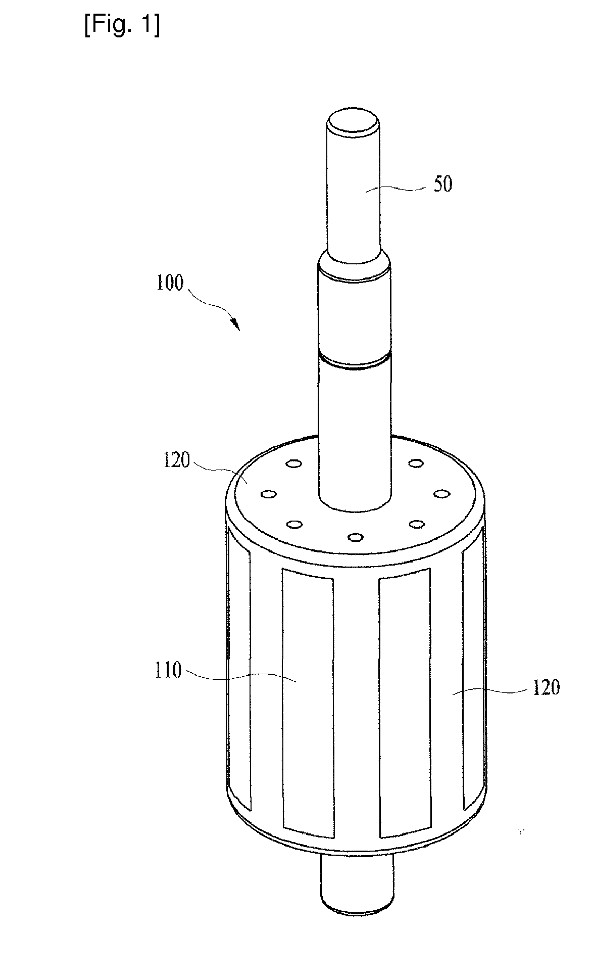
NEW MOTECH
View PDF5 Cites 13 Cited by
  • Summary
  • Abstract
  • Description
  • Claims
  • Application Information

AI Technical Summary

Benefits of technology

The present invention is a rotor for a motor that has a simple manufacturing process and low cost. It also has a new structure that allows the user to still get the motor to work even if it is not perfectly straight.

Problems solved by technology

First, because the mold of the rotor shape must be manufactured for the insert injection molding, it cause expensive manufacturing costs and the manufacturing process is complicated.
Second, because the inside of the rotor and considerable portions of the outer face of the rotor are made of plastic resin, the rotor requires a great deal of resin and a great amount of resin is lost during the molding work, and hence, manufacturing costs are increased.
Third, the rotor core 110 is generally manufactured using laminated thin steel sheets, but in the case that thin steel sheets are not laminated exactly vertically but laminated somewhat slantly without even straightness, because the rotor core is not inserted well into the mold, the insert injection molding is impossible and there is a high defection rate.

Method used


Image

  • Rotor for motor
  • Rotor for motor
  • Rotor for motor

Examples


Embodiment Construction

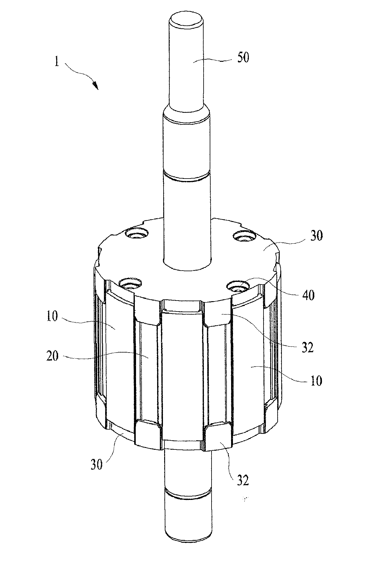
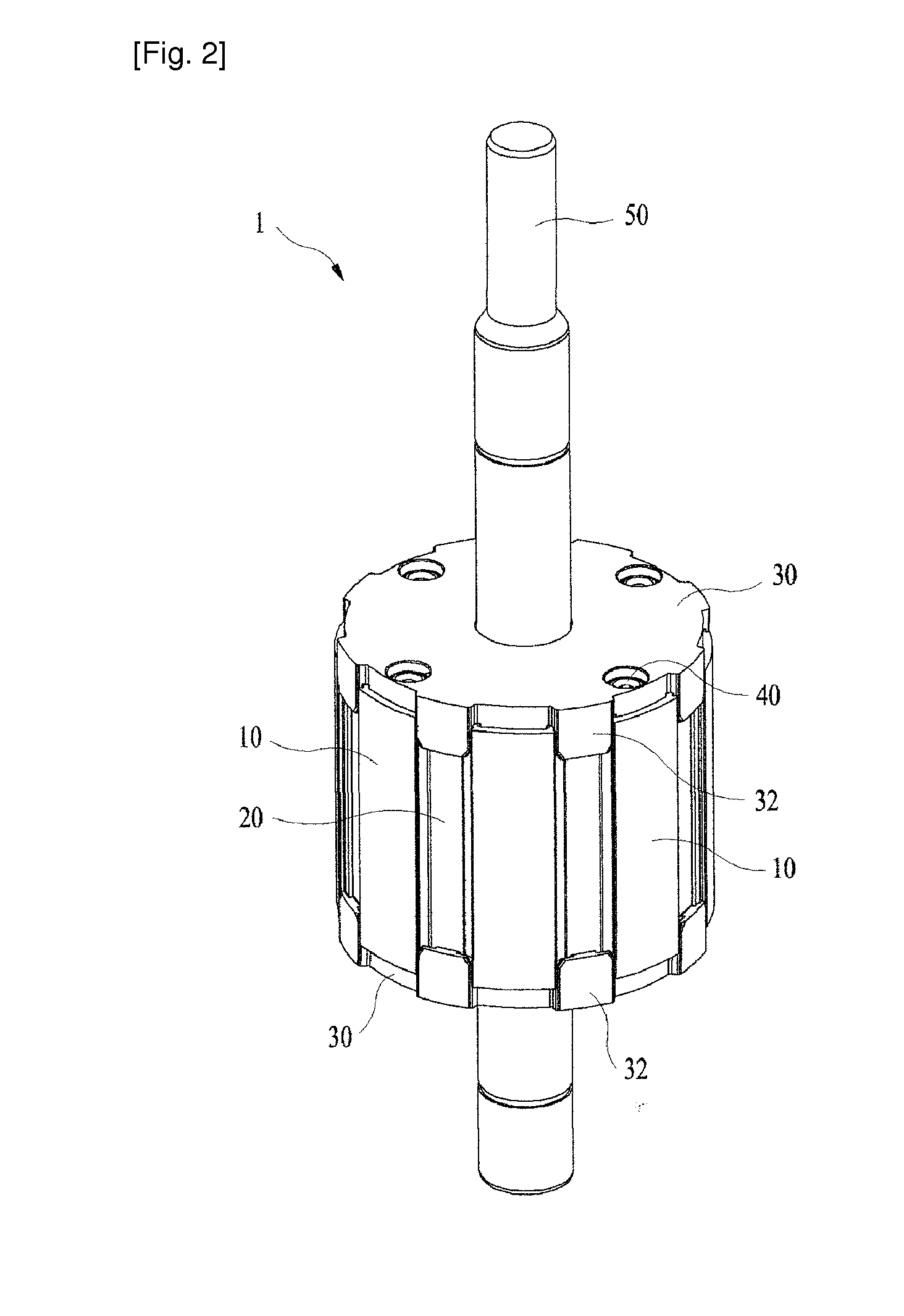
[0025]FIG. 2 is a perspective view of a rotor 1 for a motor according to the present invention, and FIG. 3 is a perspective view showing a state where one rotor cover is removed from the rotor 1 for the motor according to the present invention.

[0026]As shown in FIGS. 2 and 3, the rotor 1 according to the present invention includes a rotor core 10, magnets 20, rotor covers 30, a rivet 40, and a shaft 50.

[0027]The rotor core 10 is manufactured in such a fashion that a plurality of steel sheets are laminated and has a structure that a plurality of magnets 20 are insertable into the rotor core 10. Moreover, the rotor core 10 has a hole through which a shaft 50 penetrates into a central portion of the rotor core 10. The shaft 50 is fixed at the central portion of the rotor core 10 so as to rotate with the rotor core 10.

[0028]The rotor 100 according to the prior art illustrated in FIG. 1 has a structure that the magnets embedded inside the rotor core 110 are not exposed to the outside, bu...


PUM


Abstract

Disclosed therein is a rotor for a motor. The rotor includes: a rotor core including an annular ring having a shaft hole formed at a central portion thereof, a plurality of yokes formed around the annular ring, and magnet insertion holes formed between the neighboring yokes; magnets respectively inserted into the magnet insertion holes; and a pair of rotor covers each having a ring plate, which has a shaft insertion hole formed at a central portion thereof, and a plurality of stoppers protrudingly formed around the ring plate. A pair of the rotor covers are joined to an upper portion and a lower portion of the rotor core in such a fashion that the stoppers are respectively located at side portions of the magnet insertion holes.

Description

TECHNICAL FIELD[0001]The present invention relates to a rotor for a motor. More particularly, the present invention relates to a rotor of a new structure for a motor, which is simple in manufacturing process and can reduce manufacturing costs.BACKGROUND ART[0002]In general, a motor includes a stator and a rotor, and the rotor has various kinds and forms. The present invention relates to a rotor having a permanent magnet embedded inside a rotor core.[0003]A rotor 100 having the above form according to a prior art is illustrated in FIG. 1.[0004]As shown in FIG. 1, the rotor 100 according to the prior art includes a rotor core 110 in which a plurality of magnets (not shown) are inserted, and a molding part 120 made of plastic resin, such as PBT resin and formed around the core 110. A shaft 50 joined to a central portion of the rotor core 110 is rotated by the rotation of the rotor core 110 to rotate a load connected to the shaft.[0005]In the conventional rotor 100, the molding part 120...

Claims


Application Information

Patent Timeline
Patent Type & Authority Applications(United States)
IPC IPC(8): H02K1/27
CPCH02K1/27H02K1/2773H02K1/28H02K1/276
Inventor JANG, JEONG CHEOLLEE, JI MIN
Owner NEW MOTECH
Learn More