Stator and rotating electric machine including the same

a technology of rotating electric machines and rotating shafts, which is applied in the direction of dynamo-electric machines, electrical devices, windings, etc., can solve the problem that the actual temperature of rotating electric machines cannot be known, and achieve the effect of excellent effect and accurate detection

Active Publication Date: 2014-07-10
DENSO CORP
View PDF10 Cites 30 Cited by
  • Summary
  • Abstract
  • Description
  • Claims
  • Application Information

AI Technical Summary

Benefits of technology

[0007]It is thus desired to provide a stator that has a configuration enabling accurate temperature detection of a coil winding.
[0009]According to this configuration, the slots of the stator are formed such that the conductors are housed and arrayed. The temperature sensor is included that is located within at least one of the slots. Therefore, an excellent effect can be achieved in that the temperature of the conductors can be accurately detected by the temperature sensor located in the slots, without being affected by drafts of cooling air and the like.

Problems solved by technology

As a result, a problem occurs in that the actual temperature of the rotating electric machine cannot be known.

Method used


Image

  • Stator and rotating electric machine including the same
  • Stator and rotating electric machine including the same
  • Stator and rotating electric machine including the same

Examples


first embodiment

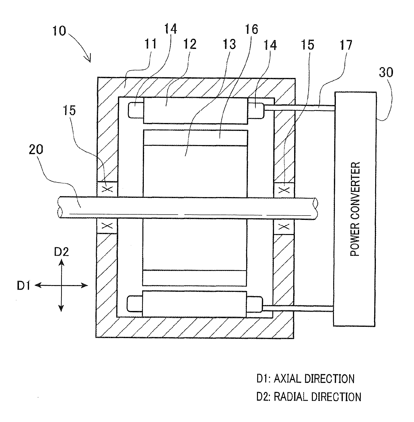
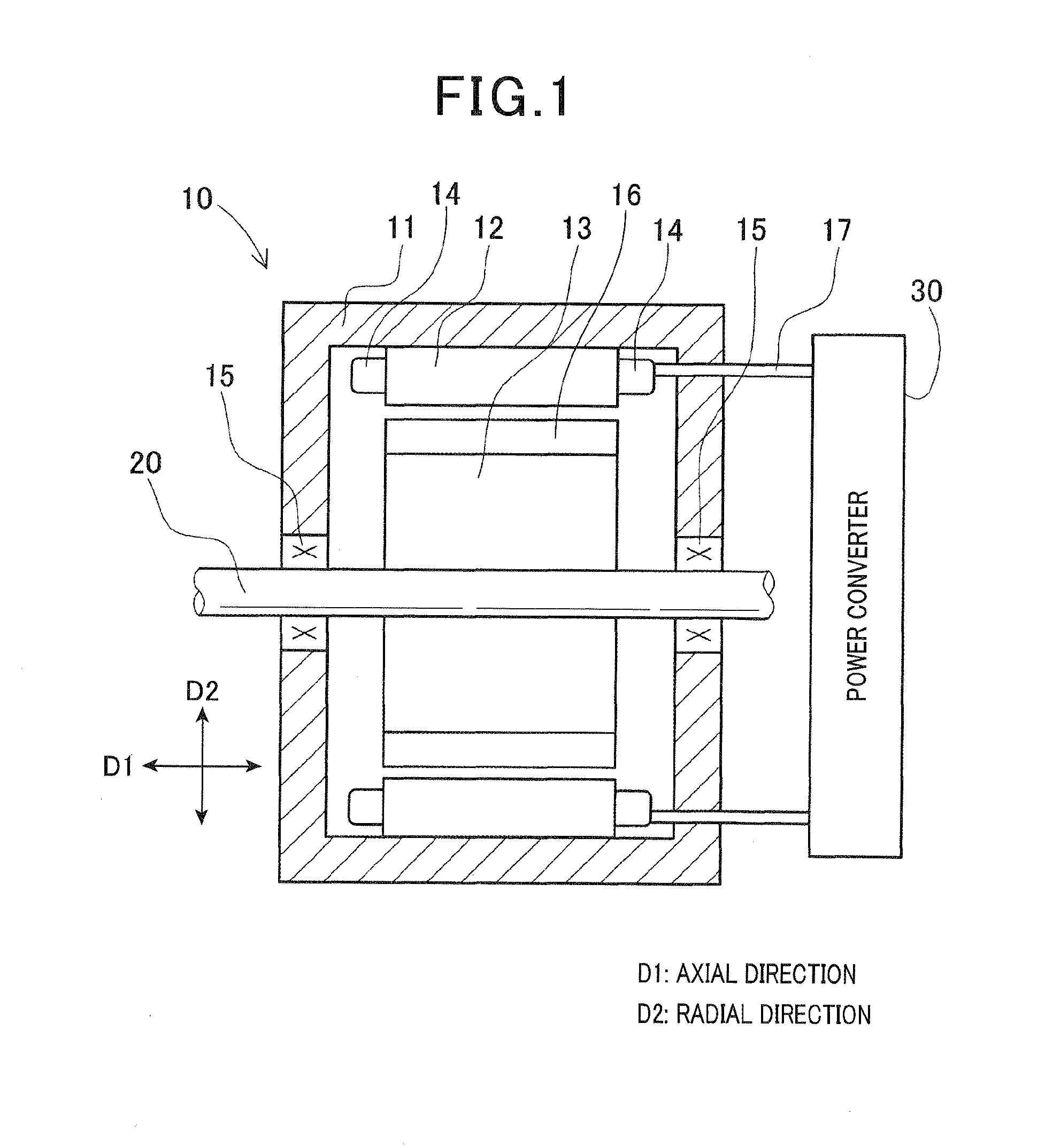
[0026]A rotating electric machine 10 shown in FIG. 1 is an example of an inner-rotor motor generator. In the rotating electric machine 10, a stator 12, a rotor 13, a rotating shaft 20, and the like are provided within a case member 11. An input / output line 17 and the like connect the rotating electric machine 10 and a power converter 30.

[0027]The case member 11 of the rotating electric machine 10 and a case member of the power converter 30 are formed separately and fixed to each other by a fixing means. Alternatively, the case member 11 of the rotating electric machine 10 and the case member of the power converter 30 are integrally formed. The fixing means in the former instance is, for example, nuts and bolts, male and female screws, through-holes and split pins, joining by welding and the like, or crimping of end pieces. Two or more of the fixing means may be selected accordingly and used in combination to fix the case member 11 of the rotating electric machine 10 and the case mem...

second embodiment

[0059]According to the above-described first embodiment, an example is given in which the temperature sensor 22 is provided in the wedge 21a or the wedge 21c. On the other hand, according to a second embodiment, the temperature sensor 22 is disposed as follows. The wedges 21 or 21b are fitted into the slots 12b. In this state, the conductors 18 are fixed by an impregnating process using an insulating resin. The wedges 21 or 21b are then pulled out, thereby forming spaces 24a. The temperature sensor 22 is disposed within the space 24a.

[0060]A configuration according to the second embodiment will be described with reference to FIGS. 11 and 12.

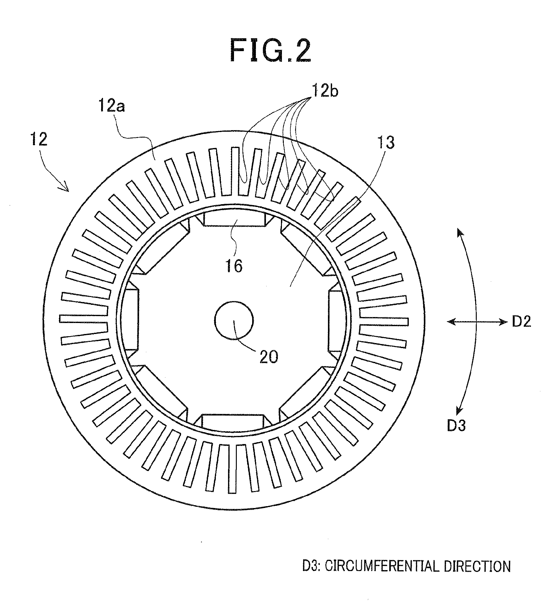
[0061]As shown in FIGS. 11 and 12, the conductors 18 are stacked and arrayed within each slot 12b. The wedges 21 are fitted between the radial-direction end surfaces 181, 182 of the arrayed conductors 18 and the opposing radial-direction wall surfaces 12b1, 12b2 of the slot 12b. However, the wedge 21 may be disposed on only either of the end sur...


PUM


Abstract

A stator includes a stator core, a winding, and a temperature sensor. In the stator core, a plurality of slots are formed in a circumferential direction of the stator. The winding is formed by a plurality of conductors which are housed in the slots and are electrically connected. The slots are formed such that a predetermined number of the conductors are housed and arrayed in a radial direction of the stator. The temperature sensor is located in at least one of the slots and detects temperature of the conductors.

Description

CROSS-REFERENCE TO RELATED APPLICATION[0001]This application is based on and claims the benefit of priority from earlier Japanese Patent Application No. 2013-001719 filed on Jan. 9, 2013, the description of which is incorporated herein by reference.BACKGROUND[0002]1. Technical Field[0003]The present invention relates to a stator capable of performing accurate temperature detection of a coil winding and a rotating electric machine including the stator.[0004]2. Related Art[0005]In a rotating electric machine, a coil winding is provided on a stator or a rotor. An electric current flows to the coil winding, when the rotating electric machine is driven. As a result, a conductor of the coil winding generates heat based on the electrical resistance of the conductor, and then temperature of the coil winding rises. Therefore, a technique is disclosed in which a temperature sensor is provided in the coil winding to detect the temperature (for example, refer to JP-A-2011-223673).[0006]However,...

Claims


Application Information

Patent Timeline
Patent Type & Authority Applications(United States)
IPC IPC(8): H02K11/00
CPCH02K11/0047H02K11/25H02K3/34H02K3/345H02K3/48H02K11/00H02K11/20H02K2213/03
Inventor TAKAHASHI, YUKISUZUKI, HIDEAKISEGUCHI, MASAHIRO
Owner DENSO CORP
Why Eureka
Try Eureka