
Method for displaying three-dimensional integral images using mask and time division multiplexing

Active Publication Date: 2014-07-10
DONGSEO UNIV TECH HEADQUARTERS
View PDF3 Cites 7 Cited by
  • Summary
  • Abstract
  • Description
  • Claims
  • Application Information

AI Technical Summary

Benefits of technology

The patent describes a way to create 3D images using a mask and time division multiplexing. This method helps to achieve higher resolution in depth-based imaging and provides a realistic 3D image with a wider depth feeling.

Problems solved by technology

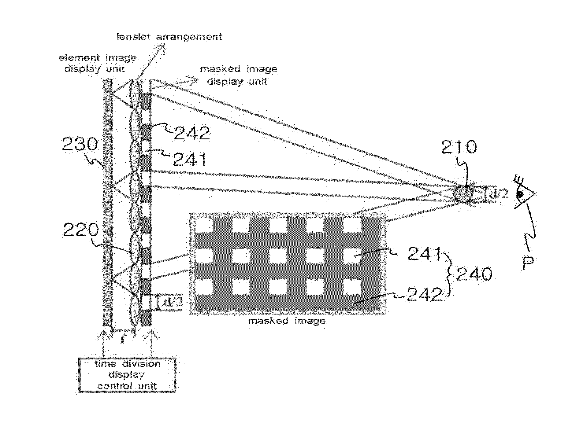
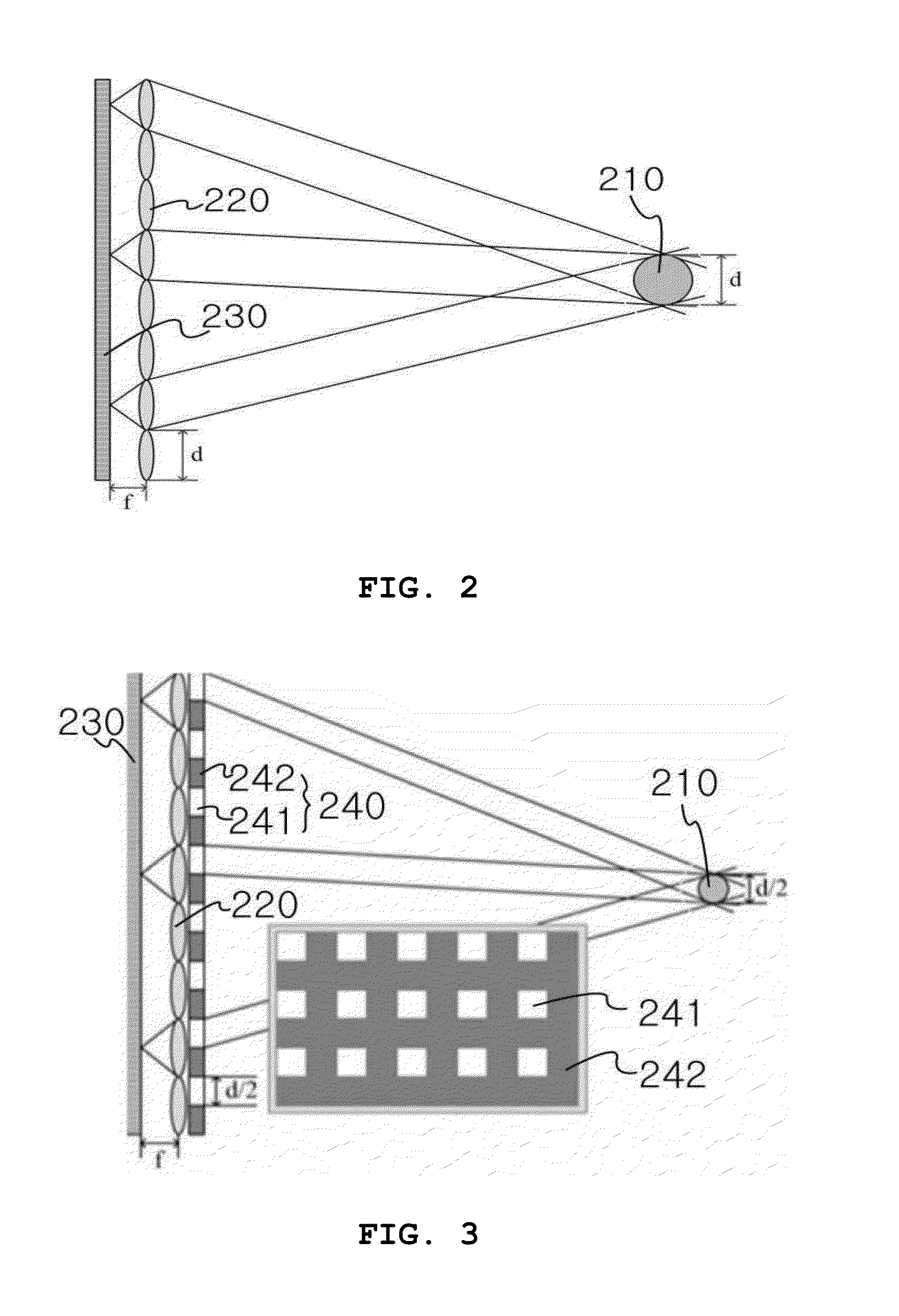
The above mentioned occasion is called a depth-based direct imaging method, by which it is possible to make maximum the region of the depth indicating a three-dimensional image; however it is disadvantageous in that the resolution of the three-dimensional image 210 is low.

Method used


Image

  • Method for displaying three-dimensional integral images using mask and time division multiplexing
  • Method for displaying three-dimensional integral images using mask and time division multiplexing
  • Method for displaying three-dimensional integral images using mask and time division multiplexing

Examples


Embodiment Construction

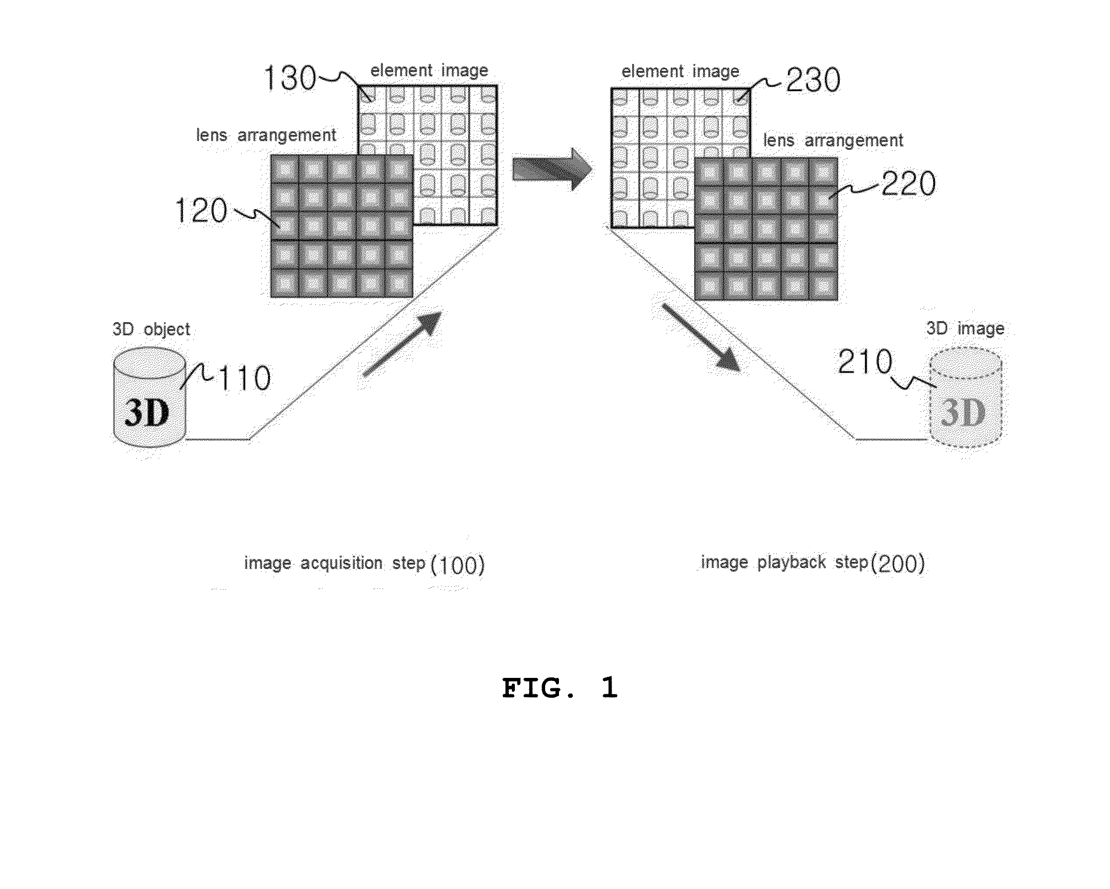
[0048]The method for displaying three-dimensional integral images using a mask and a time division multiplexing according to the present invention has features in that element images 130 and 230 obtained from a three-dimensional object 110 are passed through a lenslet 220 and a mask 240 for thereby displaying a three-dimensional image 210 in a space. The mask 240 is formed of a blocking region 242 through which an element image 230 does not pass, and a transmission region 241 through which an element image 230 cannot pass for thereby displaying a three-dimensional image 210.

[0049]The mask 240 is configured in such a way that the positions of the transmission region 241 and the blocking region 242 alternate from each other over time in sequence for thereby displaying a three-dimensional image 210.

[0050]The method for displaying three-dimensional integral images using a mask and a time division multiplexing according to the present invention will be described in details with reference...


PUM


Abstract

A method for displaying three-dimensional integral images using a mask and a time division multiplexing which is configured in such a way that a three-dimensional image is displaced in a space as an element image obtained from a three-dimensional object is passed through a lenslet and a mask, the mask consisting of a blocking region through which an element image does not pass and a transmission region through which an element image passes, for thereby displaying three-dimensional images. The present invention is advantageous to play back a three-dimensional image the resolutions of which are enhanced in a depth-based integral imaging method using a time division display of an element image and a masked image.

Description

TECHNICAL FIELD[0001]The present invention relates to a method for displaying three-dimensional integral images using a mask and a time division multiplexing, and in particular to a method for displaying three-dimensional integral images using a mask and a time division multiplexing which is configured in such a way that a, three-dimensional image is displaced in a space as an element image obtained from a three-dimensional object is passed through a lenslet and a mask, the mask consisting of a blocking region through which an element image does not pass and a transmission region through which an element image passes, for thereby displaying three-dimensional images.BACKGROUND ART[0002]There are lots of researches working on a three-dimensional image and an image playback technology, which technology currently gathers huge interesting throughout the world.[0003]The image-related technology advances more and more, so the images become highly integral.[0004]Thanks to that, the three-di...

Claims


Application Information

Patent Timeline
IPC IPC(8): H04N13/04H04N13/315H04N13/307
CPCH04N13/0402H04N13/307H04N13/315H04N13/324
Inventor SHIN, DONG-HAKOH, YONG-SEOKLEE, BYUNG-GOOK
Owner DONGSEO UNIV TECH HEADQUARTERS
Learn More