Chemically modified ion mobility separation apparatus and method

Active Publication Date: 2017-12-21
EXCELLIMS CORP
View PDF16 Cites 9 Cited by
  • Summary
  • Abstract
  • Description
  • Claims
  • Application Information

AI Technical Summary

Benefits of technology

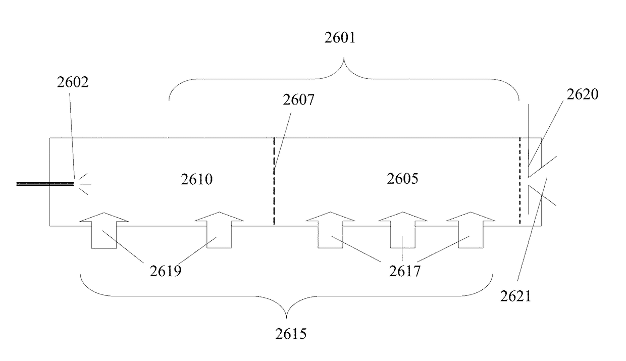
[0013]The present invention relates to a cross-directional drift tube design for an ion mobility spectrometer wherein the drift gas flow is in a direction that is substantially neither parallel nor antiparallel to the drift axis of ions. A cross-directional drift tube with one or more drift segments allows rapid drift tube clean up and flexible drift media control. A segmented drift tube is used for pre-separation of complex sample before separating samples in the subsequent drift segments. The cross flow design and segmented drift tube can also be used together

Problems solved by technology

There are many deficiencies with the current approaches for manufacturing gating devices.
This novel gating device significantly reduces the analysis of complex samples with multiple components such that lower mobility ions are not able to enter the drift tube.
However, the resolution of IMS is generally consider low, often regulating such devices to qualitative use or use in environments with low levels of interferants with respect to

Method used


Image

  • Chemically modified ion mobility separation apparatus and method
  • Chemically modified ion mobility separation apparatus and method
  • Chemically modified ion mobility separation apparatus and method

Examples


Example

[0042]The terms ion mobility separator, ion mobility spectrometer, and ion mobility based spectrometer are used interchangeably in this invention, often referred to as IMS, including time-of-flight (TOF) IMS, differential mobility spectrometers (DMS), field asymmetric ion mobility spectrometers (FAIMS) and their derived forms. A time of flight ion mobility spectrometer and its derived forms refers to, in its broadest sense, any ion mobility based separation device that characterizes ions based on their time of flight over a defined distance. A FAIMS, a DMS, and their derived forms separate ions based on their ion mobility characteristics under high values of normalized electric field.

[0043]The systems and methods of the present inventions may make use of “drift tubes.” The term “drift tube” is used herein in accordance with the accepted meaning of that term in the field of ion mobility spectrometry. A drift tube is a structure containing a neutral gas through which ions are moved un...


PUM

PropertyMeasurementUnit
Angleaaaaaaaaaa
Electric potential / voltageaaaaaaaaaa

Abstract

An ion mobility spectrometry apparatus and method wherein ions are selected using an AC gate, then separated along a drift axis while providing a drift gas flow in a direction that is substantially neither in the direction of the drift axis nor opposite to the drift axis.

Description

CROSS-REFERENCE TO RELATED APPLICATIONS[0001]The present application is a continuation-in-part of U.S. patent application Ser. No. 14 / 992,053, filed on Jan. 11, 2016, which is a continuation of application Ser. No. 14 / 214,558, filed on Mar. 14, 2014, which claims the benefit of and priority to corresponding U.S. Provisional Patent Application Ser. No. 61 / 784,324, filed on Mar. 14, 2013 and 61 / 801,722, filed on Mar. 15, 2013, and which is a continuation-in-part of U.S. patent application Ser. No. 12 / 763,092, filed on Apr. 19, 2010 and now issued as U.S. Pat. No. 9,177,770; the entire content of these applications are herein incorporated by reference.[0002]The present application is also a continuation-in-part of U.S. patent application Ser. No. 14 / 537,863, filed on Nov. 10, 2014, which is a continuation of U.S. patent application Ser. No. 13 / 475,993, filed May 20, 2012. Application Ser. No. 13 / 475,993 is a continuation-in-part of U.S. patent application Ser. No. 13 / 360,758, filed Jan...

Claims


Application Information

Patent Timeline
IPC IPC(8): H01J49/06C07B63/00G01N27/62H01J49/00
CPCH01J49/0027G01N27/622C07B63/00H01J49/061
Inventor WU, CHINGOSGOOD, MARK A.
Owner EXCELLIMS CORP
Why Eureka
Try Eureka