High performance ion mobility spectrometer apparatus and methods

Active Publication Date: 2012-09-13
EXCELLIMS CORP
View PDF3 Cites 24 Cited by
  • Summary
  • Abstract
  • Description
  • Claims
  • Application Information

AI Technical Summary

Benefits of technology

[0006]The present invention relates to, a cross-directional drift tube design for an ion mobility spectrometer wherein the drift gas flow is in a direction that is substantially neither parallel nor antiparallel to the drift axis of ions. A cross-directional drift tube with one or more drift segments allow rapid drift tube clean up and flexible drift media control. A segmented drift tube is used for pre-separation of complex sample before separating samples in the sub-sequential drift segments. The cross flow design and segmented drift tube can also be used together for enhanced separation performance. In another aspect of the present invention, at least one chemical modifier is added to the drift gas in a cross-directional gas flow that interacts selectively with at least one component of the sample in a drift tube. The component may be impurities and / or interferences in the sample whereby the chemical modifier enhances sample resolution by shifting the components drift times. The chemical modifier interaction forces, may include hydrogen bonding, dipole-dipole, and steric hindering effects, but are not limited to only these.
[0007]The present invention also relates to various aspects of Multi-Dimensional Ion Mobility Spectrometry (MDIMS) methods and apparatus. In various embodiments, the MDIMS of the present inventions differentiate themselves from conventional ion mobility spectrometry (IMS) by innovatively integrating multiple ion mobility based separation steps in one device. In various embodiments, the present invention provides higher resolution and higher sensitivity than conventional IMS devices and operational approaches. Various embodiments of the present invention provide an integrated multiple dimensional time-of-flight ion mobility spectrometric system that ionizes, separates, and detects chemical species based on their ion mobilities. These systems generally include: (a) at least one ionization source, (b) at least two drift regions, and (c) at least one ion detection device. In various embodiments, these systems separate ions in one drift dimension under one set of drift conditions; and subsequently, the separated ions are introduced into a higher dimension for further separation under the same or a different set of drift conditions. In various embodiments, the separation process can be repeated for one or more additional drift dimensions. Also, in various embodiments, the first drift dimension is used as one or more of an ionization source, reaction region or desolvation region, and drift region for the system. For example, in various embodiments, the electric field in the first drift dimension (first drift tube) can be used as a desolvation region for charged droplets.

Problems solved by technology

However, the resolution of IMS is generally consider low, often regulating such devices to qualitative use or use in environments with low levels of interferants with respect to the substances of interest.
Interfering chemical and / or biological molecules can have very similar ion mobilities which in turn can significantly limit detecting and identifying low levels of the targeted chemical and / or biological molecules in the sample.
The present state of the art ion mobility spectrometers lack the ability to directly reduce the occurrence of interfering chemical and / or biological molecules in a sample's analysis.

Method used


Image

  • High performance ion mobility spectrometer apparatus and methods
  • High performance ion mobility spectrometer apparatus and methods
  • High performance ion mobility spectrometer apparatus and methods

Examples


Embodiment Construction

[0019]Unless otherwise specified in this document the term “ion mobility based spectrometer” is intended to mean any device that separates ions based on their ion mobilities and / or mobility differences under the same or different physical and / or chemical conditions, the spectrometer may also include detecting the ions after the separation process. Many embodiments herein use the time of flight type IMS as examples; the term ion mobility based spectrometer shall also include many other kinds of spectrometers, such as differential mobility spectrometer (DMS) and field asymmetric ion mobility spectrometer (FAIMS). Unless otherwise specified, the term ion mobility spectrometer or IMS is used interchangeable with the term ion mobility based spectrometer defined above.

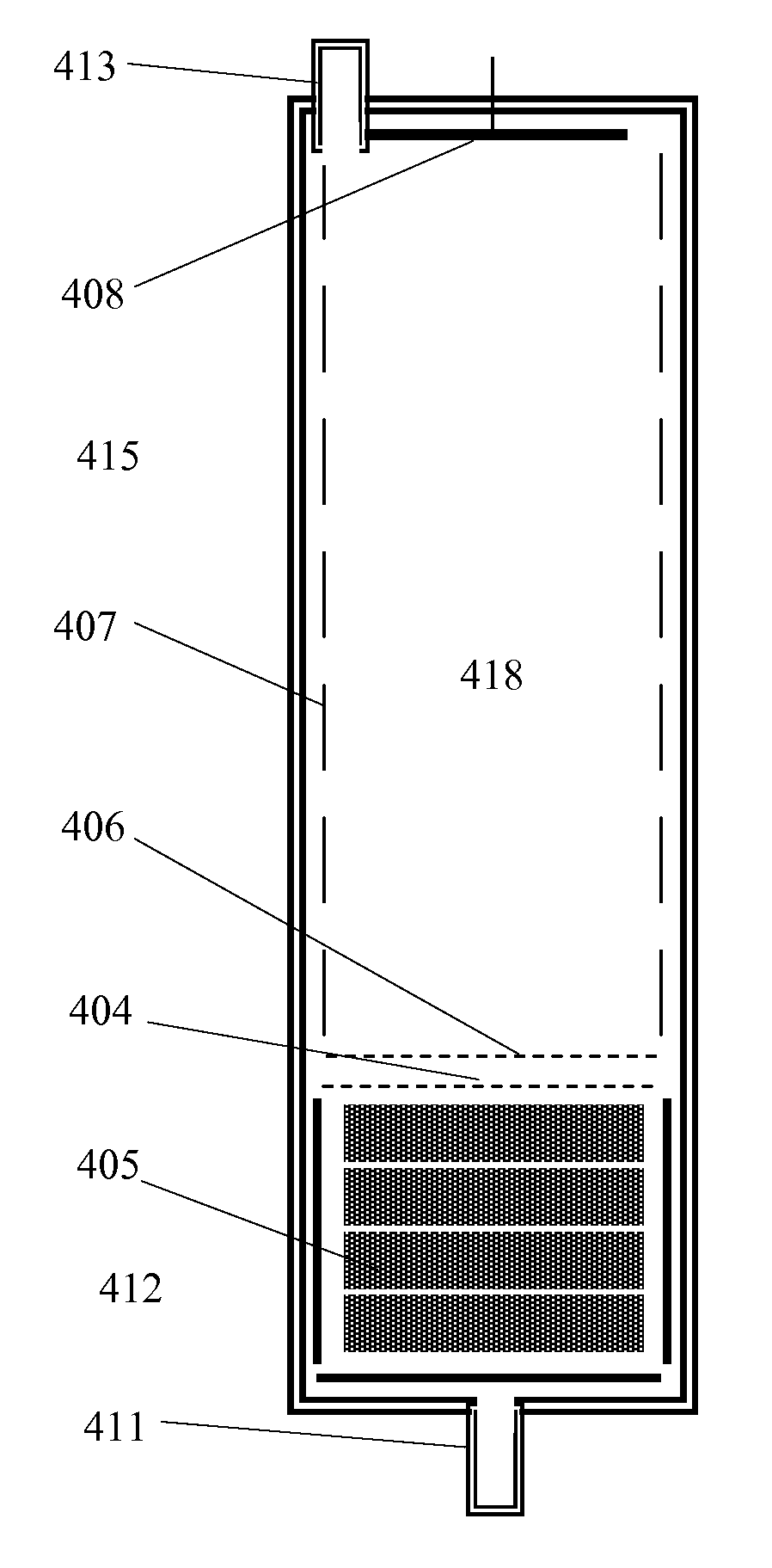
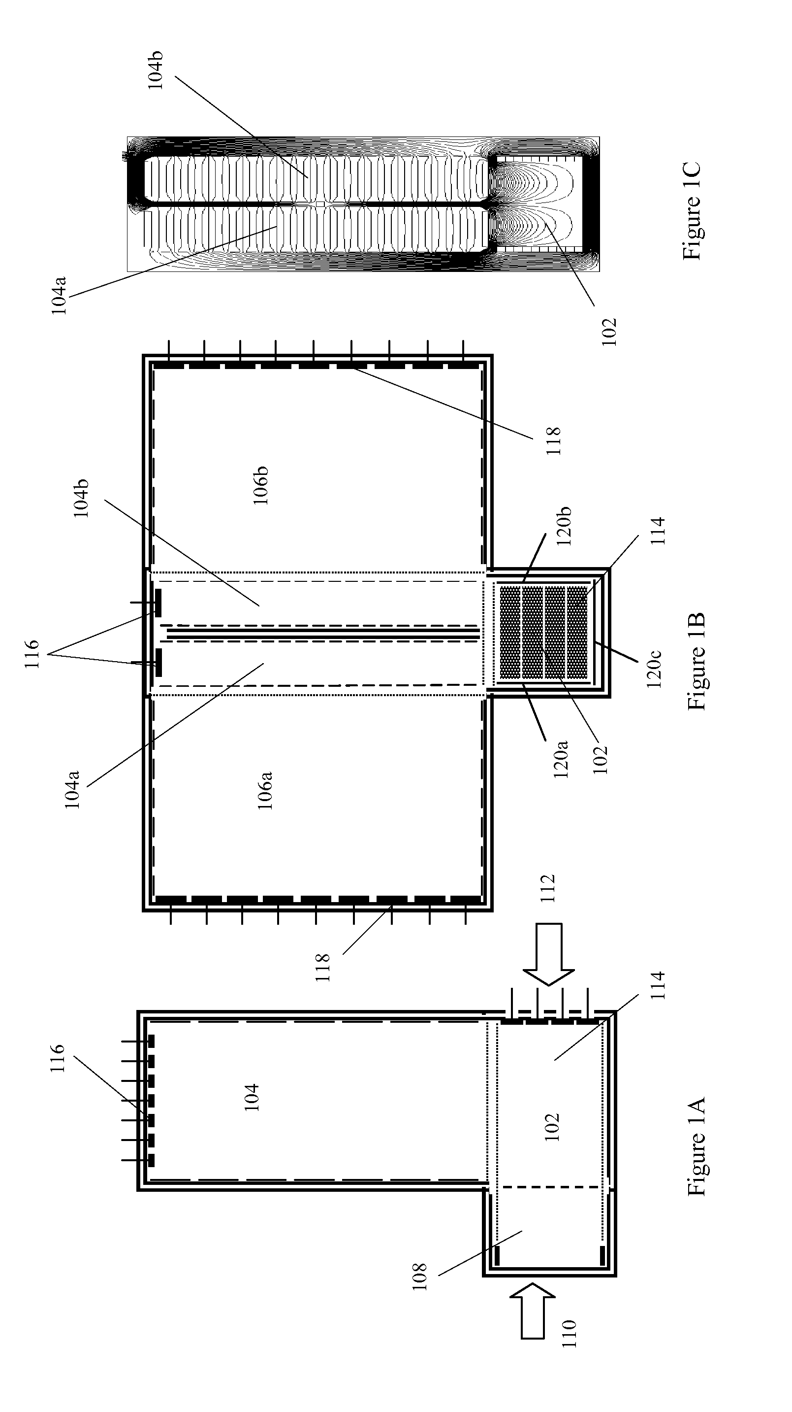
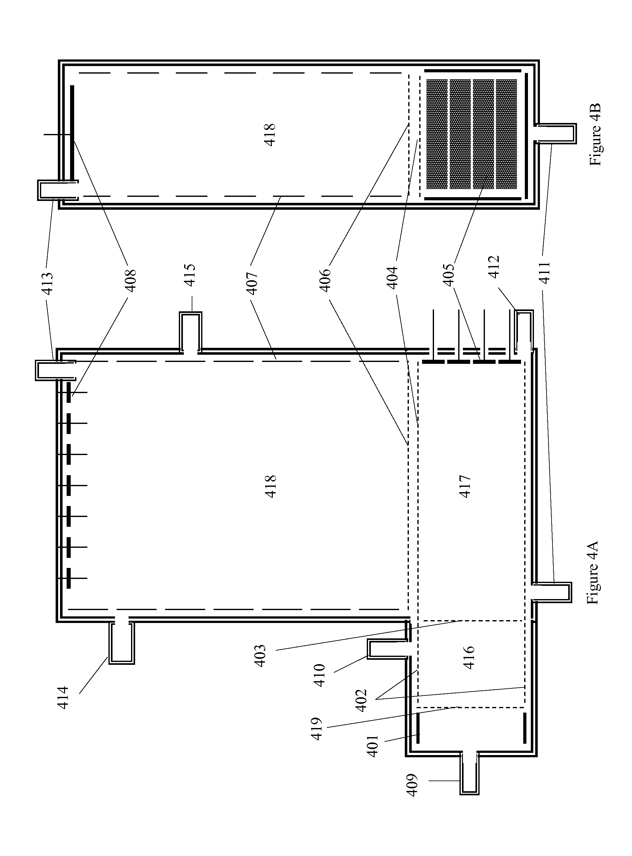
[0020]The devices and methods of the present inventions make use of “drift tubes.” The term “drift tube” is used herein in accordance with the accepted meaning of that term in the field of ion mobility spectrometry. A drift ...


PUM


Abstract

An ion mobility spectrometer wherein ions are separated along a drift axis while providing a drift gas flow in a direction that is substantially neither in the direction of the drift axis nor opposite to the drift axis. An ion mobility spectrometer and operation methods use a cross-directional gas flow in a drift tube and / or a segmented drift tube for pre-separation.

Description

CROSS-REFERENCE TO RELATED APPLICATIONS[0001]This is a continuation-in-part of U.S. patent application Ser. No. 13 / 360,758, filed Jan. 29, 2012, which is a division of application Ser. No. 12 / 471,101, filed May 22, 2009, the latter now issued as U.S. Pat. No. 8,106,352, which is a continuation of U.S. patent application Ser. No. 11 / 618,430, filed Dec. 29, 2006, the latter now issued as U.S. Pat. No. 7,576,321, which claims priority from Provisional Application 60 / 766,266, filed Jan. 2, 2006.This is a continuation-in-part of U.S. patent application Ser. No. 13 / 360,760, filed Jan. 29, 2012, which is a division of application Ser. No. 12 / 471,101, filed May 22, 2009, the latter now issued as U.S. Pat. No. 8,106,352, which is a continuation of U.S. patent application Ser. No. 11 / 618,430, filed Dec. 29, 2006, the latter now issued as U.S. Pat. No. 7,576,321, which claims priority from Provisional Application 60 / 766,266, filed Jan. 2, 2006.This is a continuation-in-part of U.S. patent appl...

Claims


Application Information

Patent Timeline
IPC IPC(8): H01J49/26
CPCG01N27/622
Inventor WU, CHINGKRUEGER, CLINTON ALAWNMIDEY, ANTHONY JOSEPHOSGOOD, MARK A.
Owner EXCELLIMS CORP
Why Eureka
Try Eureka