Flat panel display device and method for manufacturing the same
- Summary
- Abstract
- Description
- Claims
- Application Information
AI Technical Summary
Benefits of technology
Problems solved by technology
Method used
Image
Examples
first exemplary embodiment
[0070]FIG. 5 is a schematic side view of a flat panel display device according to a first exemplary embodiment of the present invention.
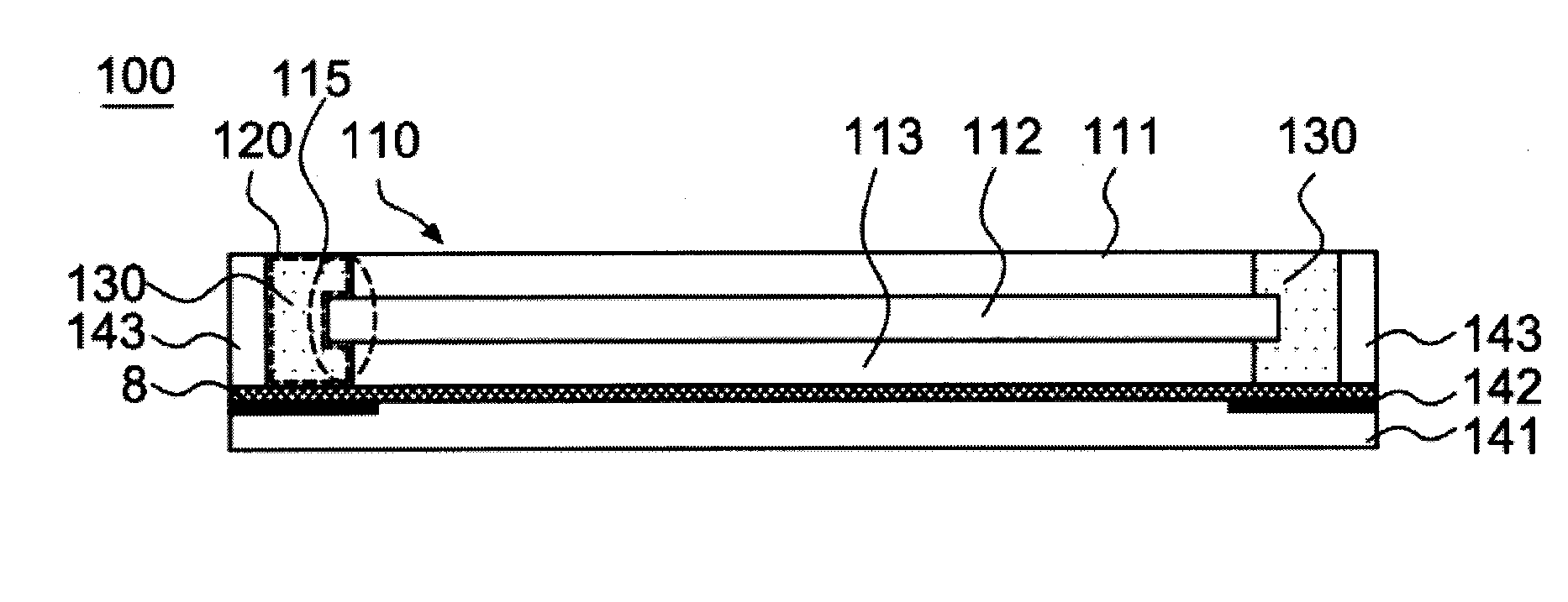
[0071]Referring to FIG. 5, a flat panel display device 200 includes a display module 210 and adhesive 230 cured while adhering to sides of the display module 210.
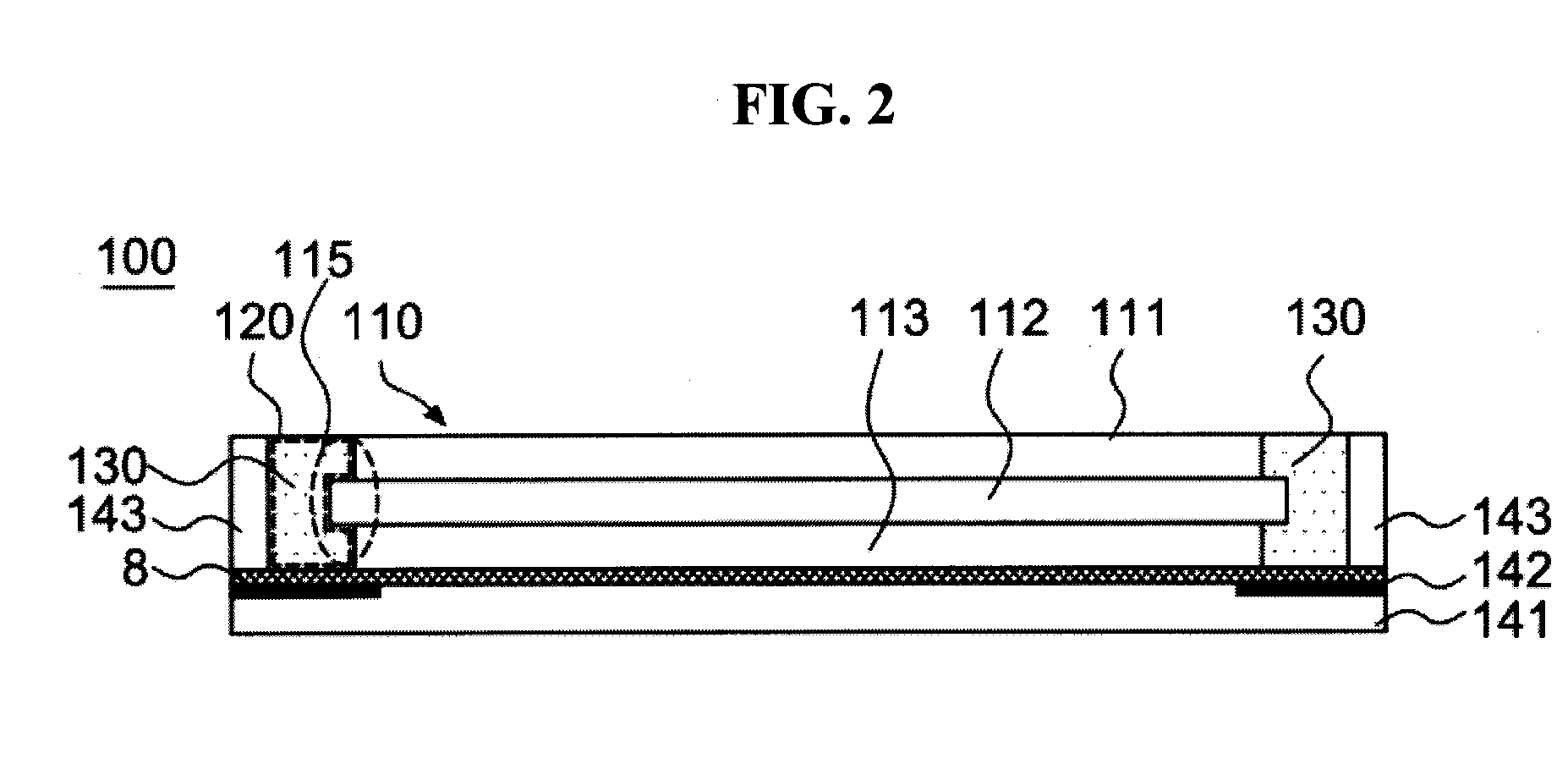
[0072]The flat panel display device 200 of the present exemplary embodiment has the same configuration as that of the aforementioned flat panel display device 100 except for a configuration of the display module 210, and thus the configuration of the display module 210 will be described in detail.
[0073]The flat panel display device 200 of the present exemplary embodiment is an electrophoretic display device, and the display module 210 includes an electrophoretic display panel 211, a touch panel 212, and a light guide plate 213.
[0074]The electrophoretic display is a display using a technology which displays colors, characters and images by using fine nanoparticles moving along a positive ele...
second exemplary embodiment
[0080]FIG. 6 is a schematic side view of a flat panel display device according to a second exemplary embodiment of the present invention.
[0081]First, referring to FIG.6, a flat panel display device includes a display module 310 and an adhesive 330 cured while adhering to sides of the display module 310.
[0082]The flat panel display device 300 of the present invention has the same configuration as those of the flat panel display devices 100 and 200 except for a configuration of the display module 310, and thus the configuration of the display module 310 will be described in detail.
[0083]The flat panel display device 300 of the present invention is an edge type liquid crystal display, and the display module 310 includes a reflection sheet 311, a light guide plate 312, an optical sheet 313, a liquid crystal display panel 314, and a touch panel 315.
[0084]The reflection sheet 311 is a member that reflects light of a light source toward the light guide plate 312 to reduce a loss of the lig...
third exemplary embodiment
[0093]FIG. 7 is a schematic side view of a flat panel display device according to a third exemplary embodiment of the present invention.
[0094]The third exemplary embodiment illustrated in FIG. 7 has the same configurations as those of the display module 310 and the adhesive 330 of the second exemplary embodiment, and thus the descriptions thereof will not be presented. A difference between the third exemplary embodiment and the second exemplary embodiment will be described in detail.
[0095]A flat panel display device 400 according to the third exemplary embodiment of the present invention includes a case 446 corresponding to a configuration in which the cover glass 341 and the outer cases 343 of the flat panel display device 300 are integrally formed.
[0096]The case 446 may have a “∈”-shaped cross section, and a display module 410 and an adhesive 430 may be included in an inner space of the case. The case 446 may be made from a transparent soft material, and the flat panel display dev...
PUM
 Abstract
Description
Claims
Application Information
 - Generate Ideas
- Intellectual Property
- Life Sciences
- Materials
- Tech Scout
- Unparalleled Data Quality
- Higher Quality Content
- 60% Fewer Hallucinations
Browse by: Latest US Patents, China's latest patents, Technical Efficacy Thesaurus, Application Domain, Technology Topic, Popular Technical Reports.
© 2025 PatSnap. All rights reserved.Legal|Privacy policy|Modern Slavery Act Transparency Statement|Sitemap|About US| Contact US: help@patsnap.com


