
Image diagnostic device and image correction method

a diagnostic device and image technology, applied in the field of image processing, can solve the problems of limited image data retrieval opportunities, and achieve the effect of evaluating the reliability of a result and high accuracy of correction

Active Publication Date: 2014-07-10
FUJIFILM HEALTHCARE CORP
View PDF11 Cites 12 Cited by
  • Summary
  • Abstract
  • Description
  • Claims
  • Application Information

AI Technical Summary

Benefits of technology

The present invention provides an image diagnostic device and an image correction method that can achieve high accuracy in correction and evaluate the reliability of the result.

Problems solved by technology

In the medical field, an opportunity for obtaining image data is limited due to the burden on patients and the procedure of applying a contrast dye, and thus it is important how the effect of the positional shift is eliminated from the obtained image data.

Method used


Image

  • Image diagnostic device and image correction method
  • Image diagnostic device and image correction method
  • Image diagnostic device and image correction method

Examples


first embodiment

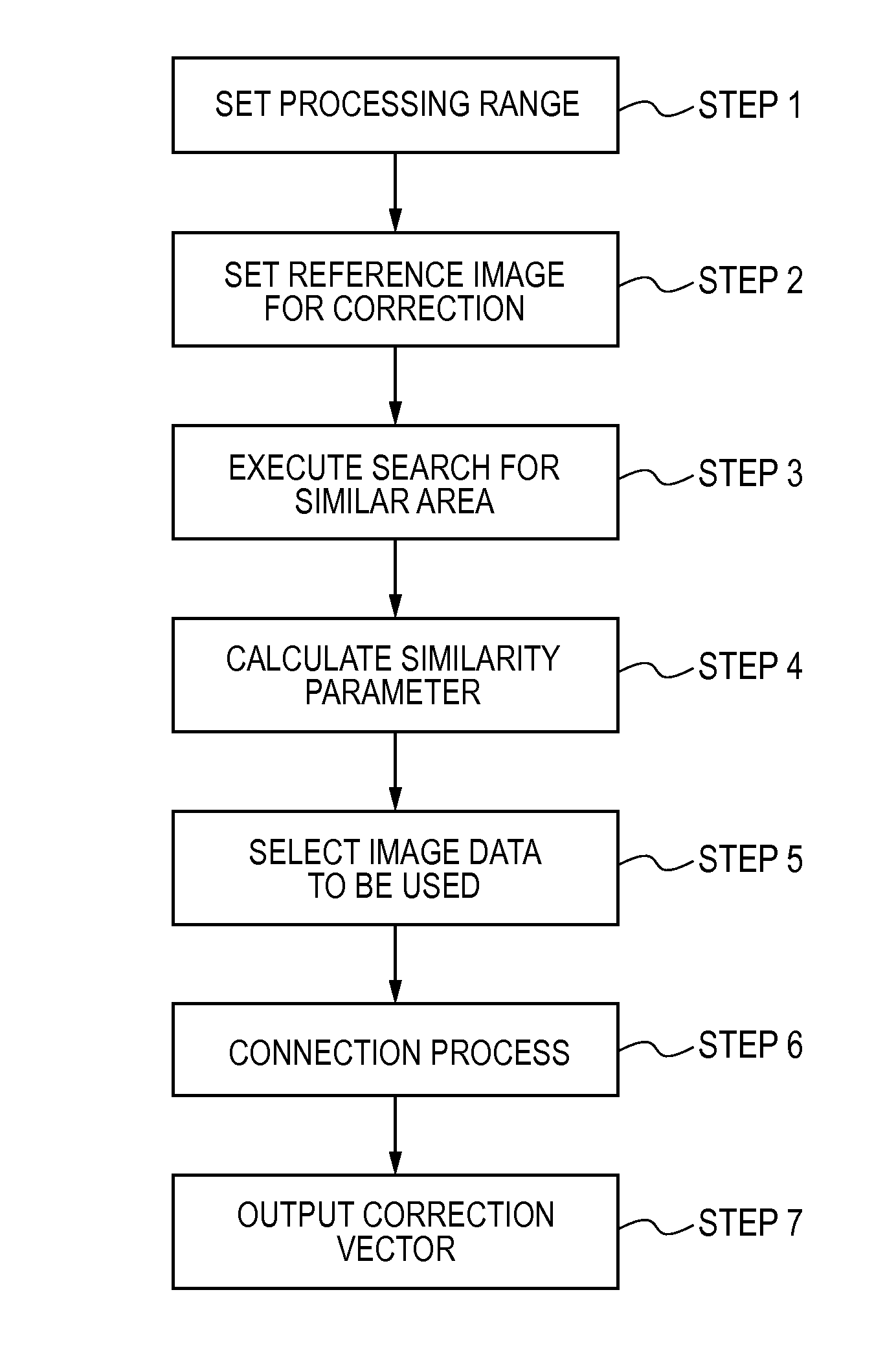
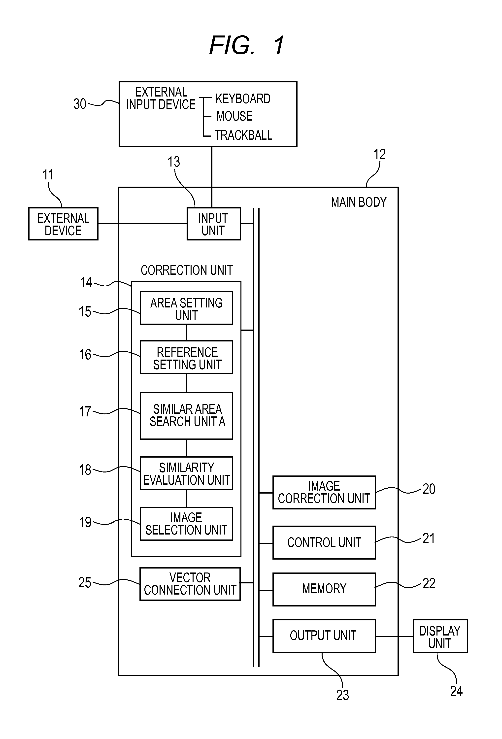
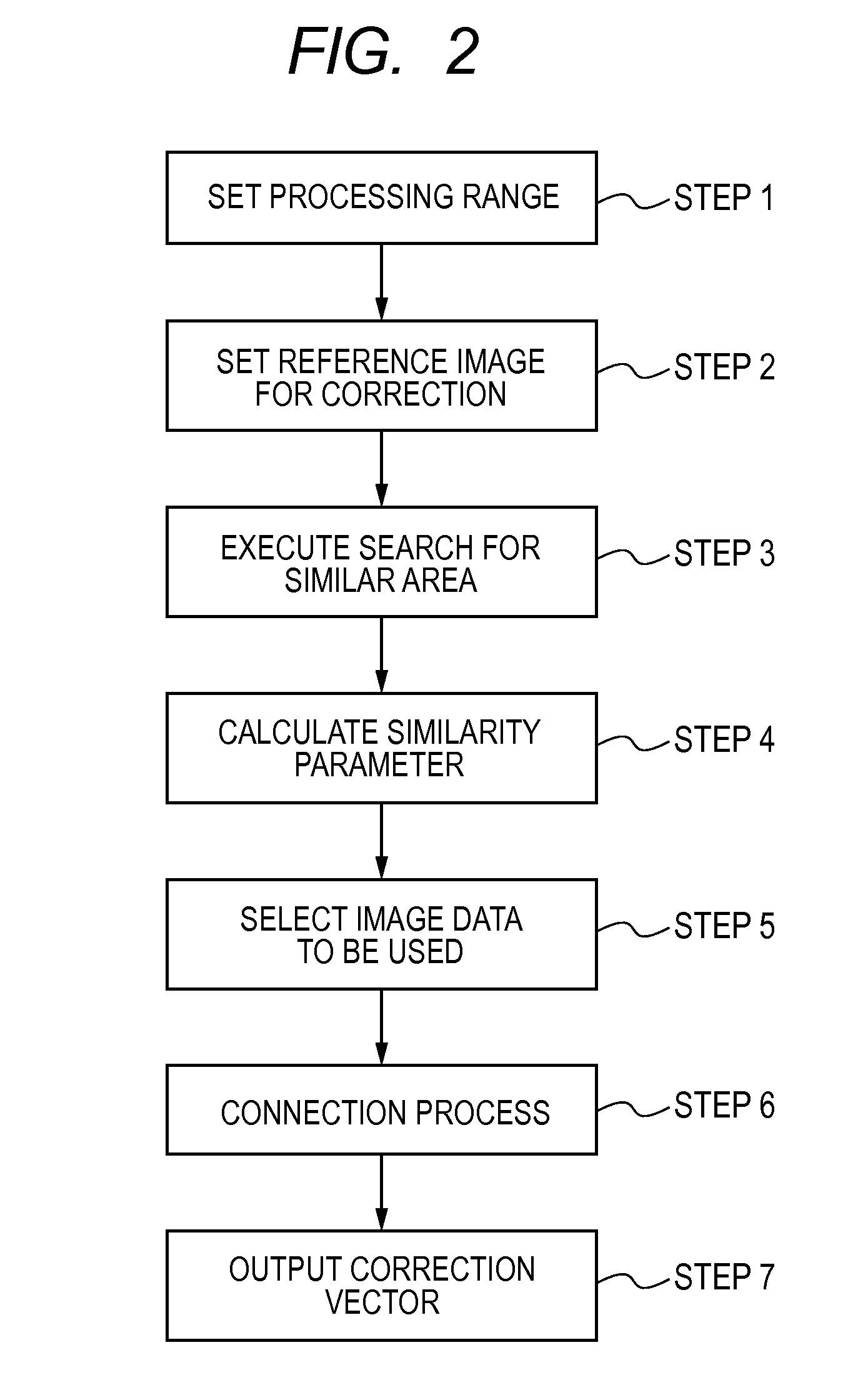
[0032]Hereinafter, a configuration example of an image diagnostic device of a first embodiment will be described using FIG. 1 to FIG. 11. The first embodiment relates to an image diagnostic device that can correct a positional shift of an imaging target for time-series image data from an external device to improve the reliability of the correction result. Specifically, the first embodiment relates to an image diagnostic device that corrects time-series image data, and is an embodiment of an image diagnostic device including a correction unit 14 that selects image data to be corrected from the time-series image data on the basis of the similarity to the reference image and outputs correction vectors indicating the positional shift of the selected image data, an image correction unit 20 that performs a correction process for the image data on the basis of the correction vectors to create corrected image data, and a display unit 24 that displays an image on the basis of the corrected i...

second embodiment

[0074]An image diagnostic device of a second embodiment is configured in such a manner that a deformation correction unit 26 is further provided to the image diagnostic device of the first embodiment and the imaging target can adapt to deformation movement. Specifically, the image diagnostic device of the second embodiment relates to an image diagnostic device having a configuration in which the deformation correction unit 26 is further provided to the image diagnostic device of the first embodiment, and the deformation correction unit 26 includes an area division unit 27 that divides an area where the correction process set by the correction unit 14 is performed and sets plural divided areas, a second similar area search unit 28 that searches for an area similar to the reference image to calculate the correction vectors for the plural divided areas, and an error correction unit 29 that performs error correction for the correction vectors calculated by the second similar area search...


PUM


Abstract

Provided is an image diagnostic device with which it is possible to correct location misalignment of an image capture subject, and to improve the reliability of the result of the correction, in time series image data. An image diagnostic device is configured of: an input part (13) which receives image data input; a correction unit (14) which computes a correction vector which denotes location misalignment of an image capture subject, and selects image data used with an image correction unit; an image correction part (20) which carries out a correction process on the image data based on the correction vector and creates corrected image data; a control part (21) which controls the correction unit and the image correction part;a memory (22) which stores the corrected image data and measurement data as stored data; an output unit (23) which outputs the stored data externally; a display unit (24) which displays the stored data; and an external input device (30) where an operator makes an input operation

Description

TECHNICAL FIELD[0001]The present invention relates to an image process for correcting the positional shift of an imaging target for time-series image data, and particularly to an image correction technique for evaluating the reliability of a correction result to realize a correction process.BACKGROUND ART[0002]A technique of a time-series image process in which an image process of addition or subtraction is performed for plural pieces of image data obtained in different time phases and temporal changes of an imaging target are extracted has been widely used in various fields. Especially, with the advanced performance of devices in the medical image diagnostic field, attention has been paid to technical development relating to not only a technique of imaging the shape of tissue that has been the mainstream, but also a function evaluation technique of evaluating the property of tissue. In the ultrasonic diagnosis, the imaging time of an image is shorter as compared to an MRI (Magnetic...

Claims


Application Information

Patent Timeline
IPC IPC(8): G06T7/00
CPCG06T7/003A61B6/032A61B6/486A61B6/5264A61B8/485A61B8/5207A61B5/055A61B6/5211A61B6/58A61B8/5215G06T2207/30004A61B6/461A61B6/469A61B6/481A61B6/5241A61B6/5235A61B8/5246A61B2576/00G06T2200/24G06T2207/20104G06T7/337G16H30/40
Inventor YOSHIKAWA, HIDEKIAZUMA, TAKASHI
Owner FUJIFILM HEALTHCARE CORP
Learn More