Haymaking machine comprising an improved deflector

a deflector and haymaking machine technology, applied in the field of haymaking machines, can solve the problems of affecting the stability of the machine, the deflector projecting at the rear of the chassis is greatly exposed to impacts, and the inability to obtain a compact machine for transportation, so as to reduce the overall dimension, reduce the centre of gravity, and work wide.

Inactive Publication Date: 2014-07-17
KUHN SA
View PDF36 Cites 13 Cited by
  • Summary
  • Abstract
  • Description
  • Claims
  • Application Information

AI Technical Summary

Benefits of technology

[0006]The present invention has the aim of proposing a haymaking machine which does not present the above-mentioned drawbacks. The machine according to the invention makes is possible to form a regular and readily delimited windrow. In addition, it is capable of having a large working width whilst maintaining, for manoeuvres and for transport, a reduced overall dimension and a low centre of gravity, favourable to stability. Finally, the invention has recourse to technical means which are relatively simple and not very expensive.

Problems solved by technology

This design does not permit a compact machine to be obtained for transport.
In addition, in this second position of the arm, the deflector projecting at the rear of the chassis is greatly exposed to impacts.
The centre of gravity of the machine is therefore higher, to the detriment of the stability of the machine, in particular during transport.
The use of a deflector and of an arm according to those of the second known machine, carried by a frame of one of these lateral pick-up and moving devices, would pose a problem with regard to overall dimension when the arm is placed in the second position above the device and the latter is folded upwards with respect to the chassis.
Elaborate kinematics for folding the pick-up and moving devices upwards could be envisaged to compensate for the overall dimension of the deflector and of the arm in the second position, at the cost, however, of a very complex and costly machine.

Method used


Image

  • Haymaking machine comprising an improved deflector
  • Haymaking machine comprising an improved deflector
  • Haymaking machine comprising an improved deflector

Examples


Embodiment Construction

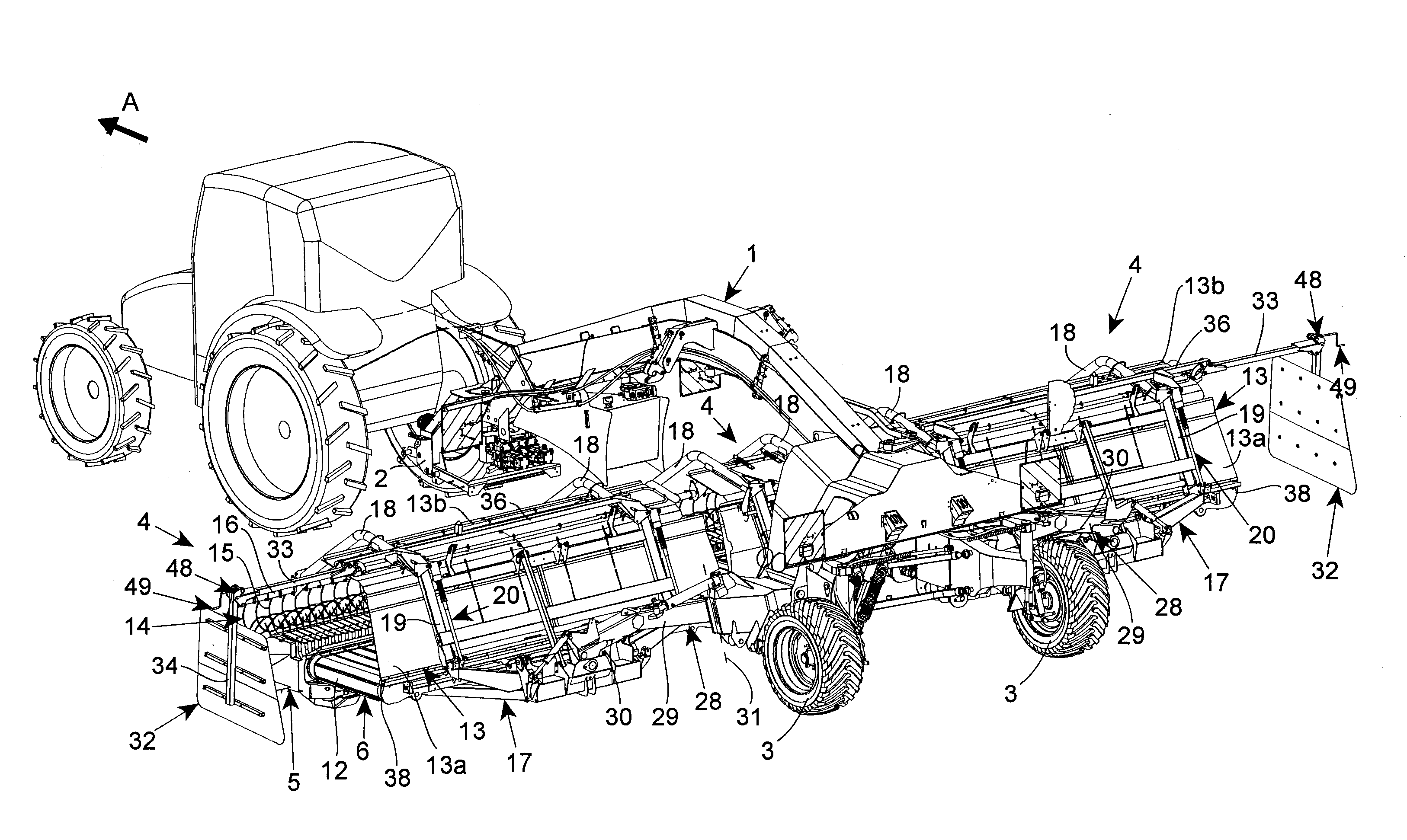
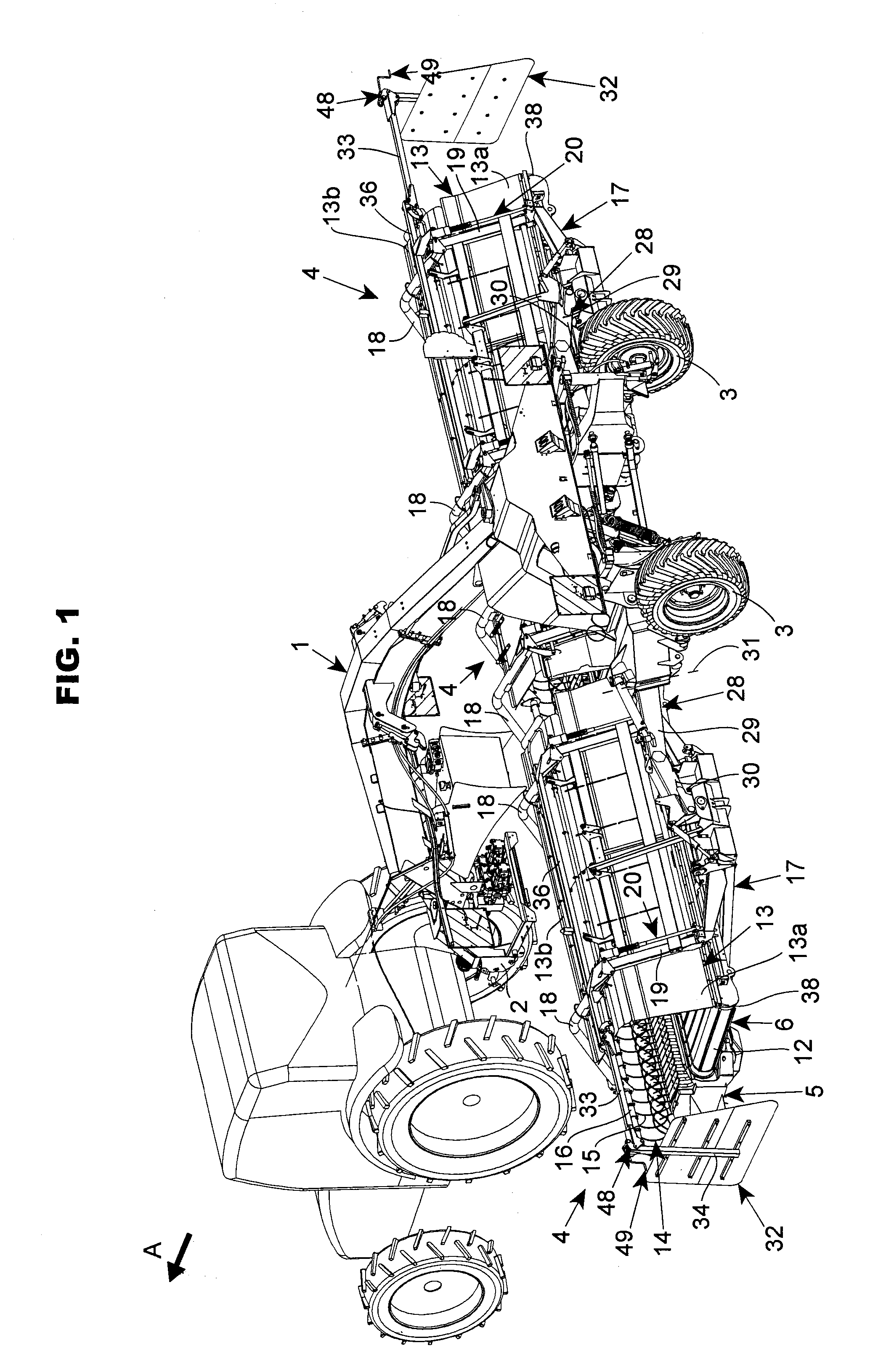
[0018]The agricultural machine according to the invention illustrated in FIG. 1 comprises a chassis 1. This chassis 1 comprises a more or less central longitudinal beam. The latter carries at its front end a hitching device 2. The latter enables the connection of the chassis 1 to a tractor so as to move the machine in a direction of advance A. A power take-off of the tractor provides the driving of the different work elements of the machine. The rear part of the chassis 1 comprises a train of wheels 3 in contact with the ground. In the following description, the terms “left”, “right”, “front”, “rear”, “rearwards”, “back” and “posterior” relate to the direction of advance A, and the terms “upper”, “upwards” and “above” are defined with respect to the ground.

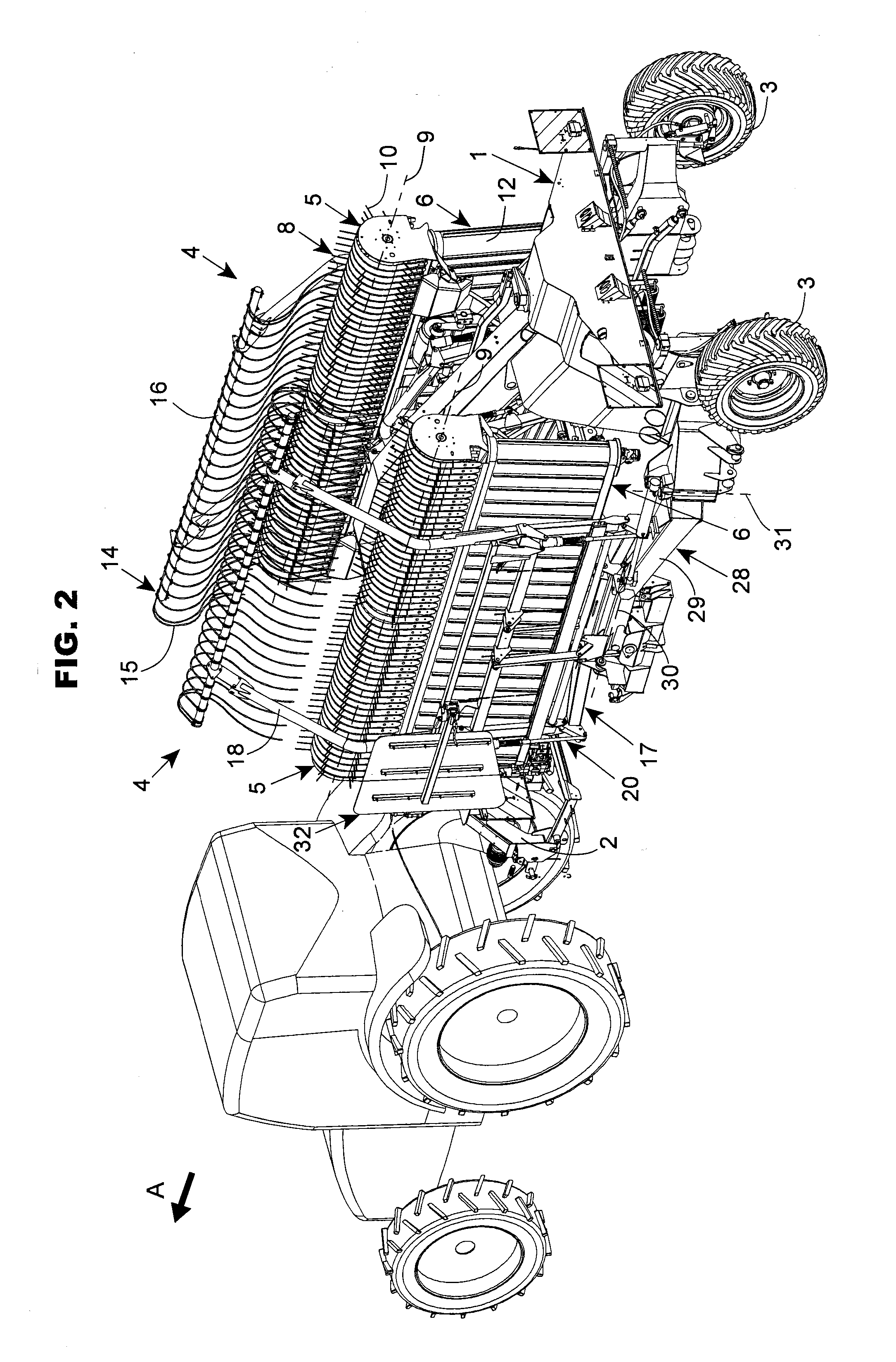
[0019]The machine comprises at least one plant pick-up and moving device 4. As can be seen from FIG. 1, this pick-up and moving device 4 is situated, relative to the direction of advance A, between the hitching device 2 and the tr...


PUM


Abstract

A haymaking machine comprises a harvesting device comprising a rotor driven about an axis which is horizontal and perpendicular to a direction of advance during work, teeth, the points of which describe a curve envelope when the rotor turns about the axis, and a conveyor moving the plants transversely to the direction of advance, the machine comprising a deflector connected to an arm connected to the harvesting device by means of an articulation, about which the arm can pivot between a first position in which the deflector is arranged, during work, beside and at a distance from a lateral end of the harvesting device, and a second position. In the second position and considering the machine during work, the deflector and the arm extend flat and at least partially above the harvesting device.

Description

BACKGROUND OF THE INVENTION[0001]1. Field of the Invention[0002]The present invention relates to a haymaking machine comprising at least one plant pick-up and moving device, comprising a rotor able to be driven about a rotation axis which is substantially horizontal and substantially perpendicular to a direction of advance of the machine in a work position, teeth with teeth points describing a curve envelope when the rotor is driven about the rotation axis, and a conveyor which moves the plants transversely to the direction of advance, the machine also comprising at least one deflector which cooperates with the pick-up and moving device so as to receive, during work, a flow of plants moved by the conveyor so as to form a windrow, the deflector being connected to an arm which is itself connected, by means of a first articulation device, to the pick-up and moving device, by means of which first articulation device the arm can be pivoted, with respect to the pick-up and moving device, ...

Claims


Application Information

Patent Timeline
Patent Type & Authority Applications(United States)
IPC IPC(8): A01D78/02A01B73/02
CPCA01B73/02A01D78/02A01D57/20A01D84/00
Inventor GANTZER, CHRISTIAN
Owner KUHN SA
Why Eureka
Try Eureka