Harvesting machine comprising an improved lubrication device

a lubrication device and harvesting machine technology, applied in the field of agricultural machines, can solve the problems of increasing the time that the machine is out of service, increasing and the user's repetitive maintenance operations, so as to improve the efficiency of harvesting and reduce the risk of omitting or neglecting the maintenance of one of the boxes. , the effect of reducing the risk of omitting or neglecting the maintenan

Active Publication Date: 2017-10-10
KUHN SA
View PDF36 Cites 0 Cited by
  • Summary
  • Abstract
  • Description
  • Claims
  • Application Information

AI Technical Summary

Benefits of technology

[0031]The primary box and the secondary box thus share the same lubricant, the circulation of which is ensured inside of each of these boxes by means of the pump connected to the primary and secondary distribution systems, as well as to the return system. Several advantages result from this design. On one hand, the periodic operations of checking the quantity and of replacement of the lubricant are simplified. Indeed, a single level of lubricant must be established, and checked from time to time, for the two boxes. In addition, the emptying of the lubricant is carried out simultaneously for the two boxes. On another hand, as the lubricant circulating in the secondary box also circulates in the primary box, the lubricant present in the secondary box is better cooled. The same applies for the secondary torque transmission means, which are therefore better able to transmit a great mechanical power. The level of lubricant can be established so that a relatively large overall volume of lubricant is available to ensure an adequate supplying with lubricant of the primary and secondary torque transmission means. However, the risk of seeing this lubricant degrade prematurely by heating and mechanical shearing, is greatly reduced because, during the operation of the machine, the lubricant is not stationary inside of the primary and secondary boxes but, on the contrary, circulates permanently therein. The lubrication of the secondary box by circulation of the lubricant makes it possible to design a secondary box of reduced dimensions. This enables the arrangement, within a machine for which the overall dimension during transport remains reduced, of conditioning elements having a large working width, in order to ensure an optimum treatment of the cut plants.

Problems solved by technology

This multiplicity of maintenance operations is tedious for the user, increases the time that the machine is out of service, and increases the risk of omitting or neglecting the maintenance of one of the boxes.
Furthermore, the lubricant contained in the secondary box is confined inside of the inner volume of this secondary box, this inner volume is, however, of small size.
The overall dimension of the latter is also limited, in its lower part, by the very close presence of the rotational mounting means of the lower conditioning element on the frame of the harvesting mechanism.
The secondary box in its entirety, and the lubricant which it contains, are therefore liable to be subject to a great heating during the work of the machine.
In addition, in the case of a fluid lubricant in which the secondary torque transmission means are in part bathed, these geometric constraints reduce the inner volume of the secondary box, within which this lubricant can be distributed, and in particular the space between the secondary torque transmission means and the walls of the secondary box.
There then arises a delicate compromise to be solved between, on one hand, a large quantity of lubricant in order to ensure a sufficient supply with lubricant of the secondary torque transmission means bathing in part in this lubricant, this large volume of lubricant in which the secondary torque transmission means paddle during their movement being able nevertheless to generate an excessive heating and an accelerated degradation of the lubricant by shearing and friction, and on another hand a reduced quantity of lubricant, which can nevertheless result in an insufficient lubrication under certain conditions.
This phenomenon is liable to produce a lack of lubrication of these transmission means, because the lubricant can distribute itself, essentially, on the internal walls and not on the secondary torque transmission means.
The problem of the supply with lubricant to the secondary torque transmission means, and also the heating of the lubricant and of the secondary box, arises acutely on a harvesting machine having a large working width and subjected to strict regulations dictating a reduced overall dimension during transport.
The large working width requires bulky and heavy conditioning elements, between which a large flow of cut plants passes.
In addition, inside of the latter, secondary torque transmission means dimensioned in an increased manner so as to resist the increased mechanical forces, tend to reduce the available volume for the lubricant.
It then becomes difficult to ensure a suitable lubrication and cooling of the secondary box as a whole.

Method used


Image

  • Harvesting machine comprising an improved lubrication device
  • Harvesting machine comprising an improved lubrication device
  • Harvesting machine comprising an improved lubrication device

Examples


Embodiment Construction

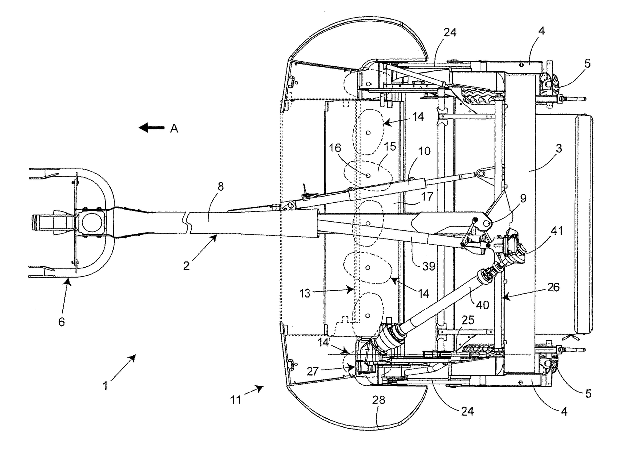
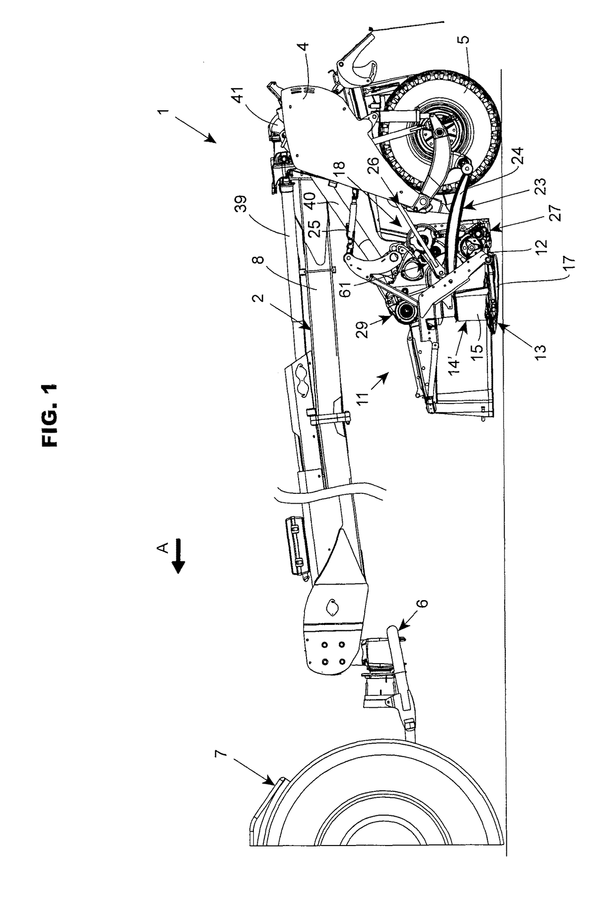
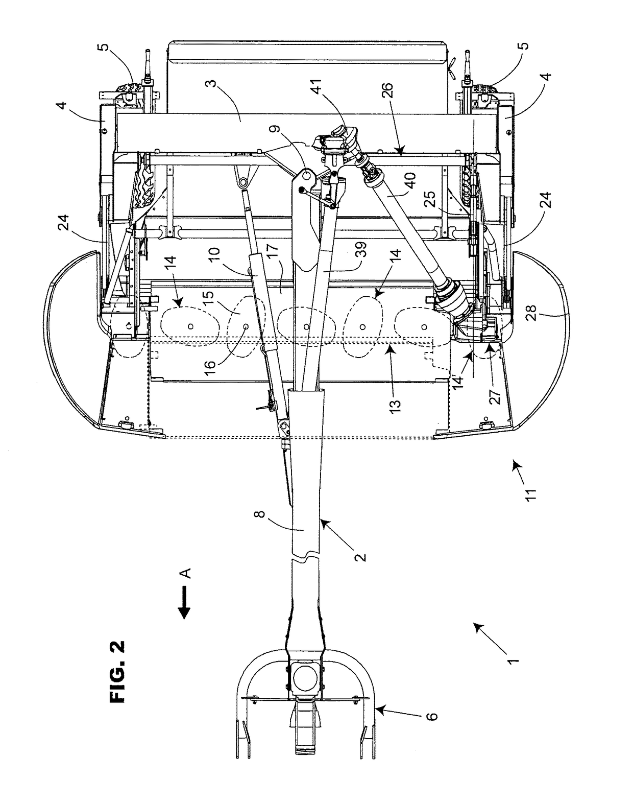
[0042]As is represented in FIGS. 1 and 2, the machine according to the invention is an agricultural machine 1 for the harvesting of plants, in particular of fodder. The machine 1 comprises a chassis 2 having in particular a transverse beam 3. The chassis 2 also comprises two lateral posts 4. Each lateral post 4 is provided with at least one wheel 5 on the ground. The chassis 2 comprises a hitching device 6 allowing the chassis 2 to be hitched to a tractor 7, represented in FIG. 1, for moving the machine 1 in a direction of advance A and for driving the different elements of the machine 1. In the remaining description, the terms “front”, “rear” and “frontal” are defined with reference to this direction of advance A, and the terms “horizontal”, “vertical”, “transverse”, “above”, “top”, “bottom”, “upper”, “lower”, “upwards”, “downwards” and “beneath” relate to the machine 1 in work situation. In the embodiment of the figures, the hitching device 6 is placed at the level of a frontal en...


PUM


Abstract

An agricultural machine includes a cutting mechanism and first and second conditioning elements driven by a transmission comprising a primary box including a first output connected to the cutting mechanism, a second output connected to the first conditioning element and a third output, connected with one another by primary transmission means, the transmission including a secondary box including an input connected to the third output and an output connected to the second conditioning element, connected with one another by secondary transmission means, the transmission comprising a lubrication device for the primary box with a pump and a primary distribution system for a lubricant towards the primary transmission means. The lubrication device comprises a secondary distribution system distributing the lubricant from the pump towards the secondary transmission means, and a return system for the lubricant from the secondary box towards the pump.

Description

BACKGROUND OF THE INVENTION[0001]Field of the Invention[0002]The present invention relates to an agricultural machine for the harvesting of plants comprising:[0003]a chassis,[0004]at least one harvesting mechanism connected to the chassis and comprising:[0005]a cutting mechanism comprising cutting elements intended for cutting plants, and[0006]a conditioning device comprising first and second contra-rotating conditioning elements liable to move away from one another and between which the plants cut by the cutting elements are intended to pass for their treatment,[0007]a transmission mechanism intended to ensure the driving of the cutting elements and of the first and second conditioning elements, and comprising:[0008]a primary box comprising:[0009]a primary casing delimiting a primary inner volume,[0010]an input shaft provided to be set in motion from a power source,[0011]a first primary output connected to the cutting mechanism,[0012]a second primary output connected to the first c...

Claims


Application Information

Patent Timeline
Patent Type & Authority Patents(United States)
IPC IPC(8): A01D43/10A01D75/00F16N7/38
CPCA01D43/10F16N7/38A01D75/00A01D43/105
Inventor WALCH, MARTIN
Owner KUHN SA
Why Eureka
Try Eureka