Direct Torque Helical Displacement Well and Hydrostatic Liquid Pressure Relief Device

a technology of hydrostatic liquid pressure relief and helical displacement well, which is applied in the direction of drilling pipes, rotary drilling, mechanical conveying drilling, etc., can solve the problems of increased risk of well collapse, and excavated well usually developing debris, etc., and achieves significant potential savings

Active Publication Date: 2014-07-17
QUEEN FRIE A R
View PDF41 Cites 16 Cited by
  • Summary
  • Abstract
  • Description
  • Claims
  • Application Information

AI Technical Summary

Benefits of technology

This patent describes a way to install a well for accessing underground resources like water. One big benefit is that it allows for easy removal from the ground at any point during construction or when there's no longer a need for the well. Additionally, if the well needs to be cleaned or reused, it offers cost-effective options compared to other types of wells. Overall, this approach provides greater flexibility and efficiency for installing and utilizing wells.

Problems solved by technology

The technical problem addressed in this patent text relates to preventing well collapses caused by unstable soil conditions or debris falling into the well while also reducing the costly measures taken to address these issues, including the use of expensive drilling fluid and increased labor expenses.

Method used


Image

  • Direct Torque Helical Displacement Well and Hydrostatic Liquid Pressure Relief Device
  • Direct Torque Helical Displacement Well and Hydrostatic Liquid Pressure Relief Device
  • Direct Torque Helical Displacement Well and Hydrostatic Liquid Pressure Relief Device

Examples


Embodiment Construction

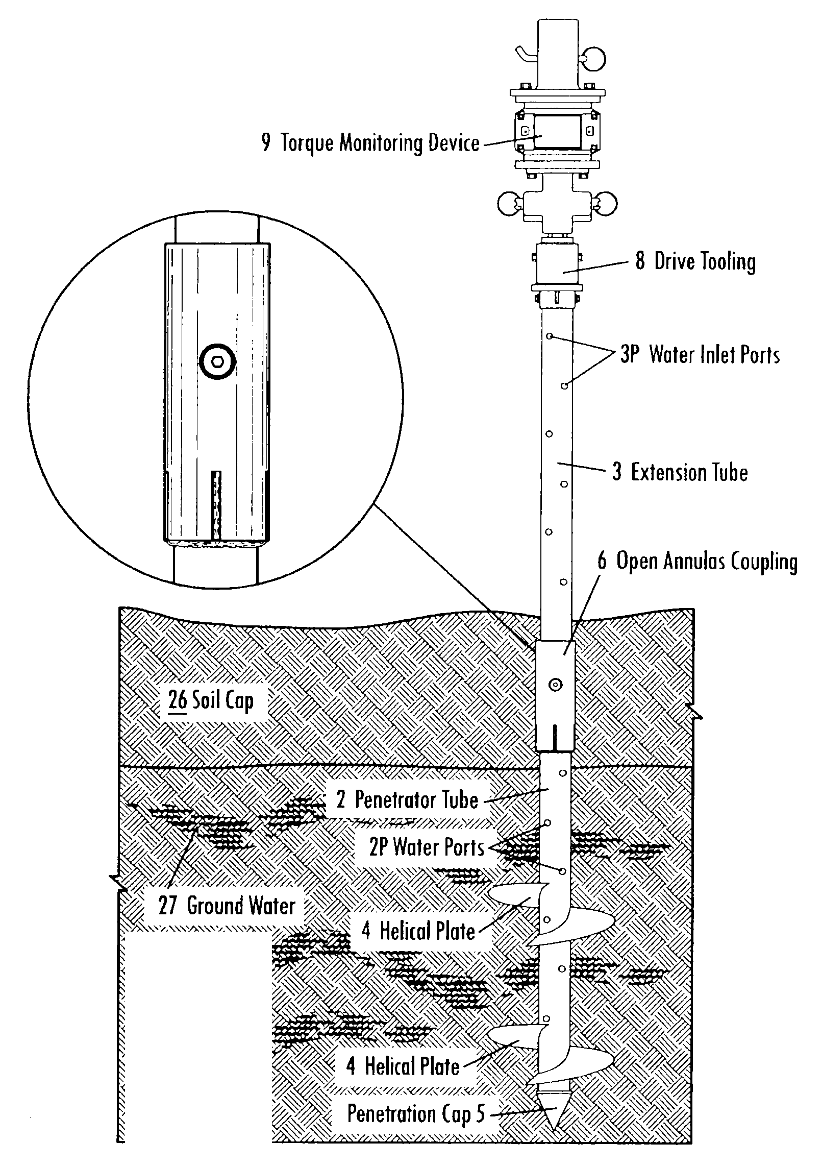
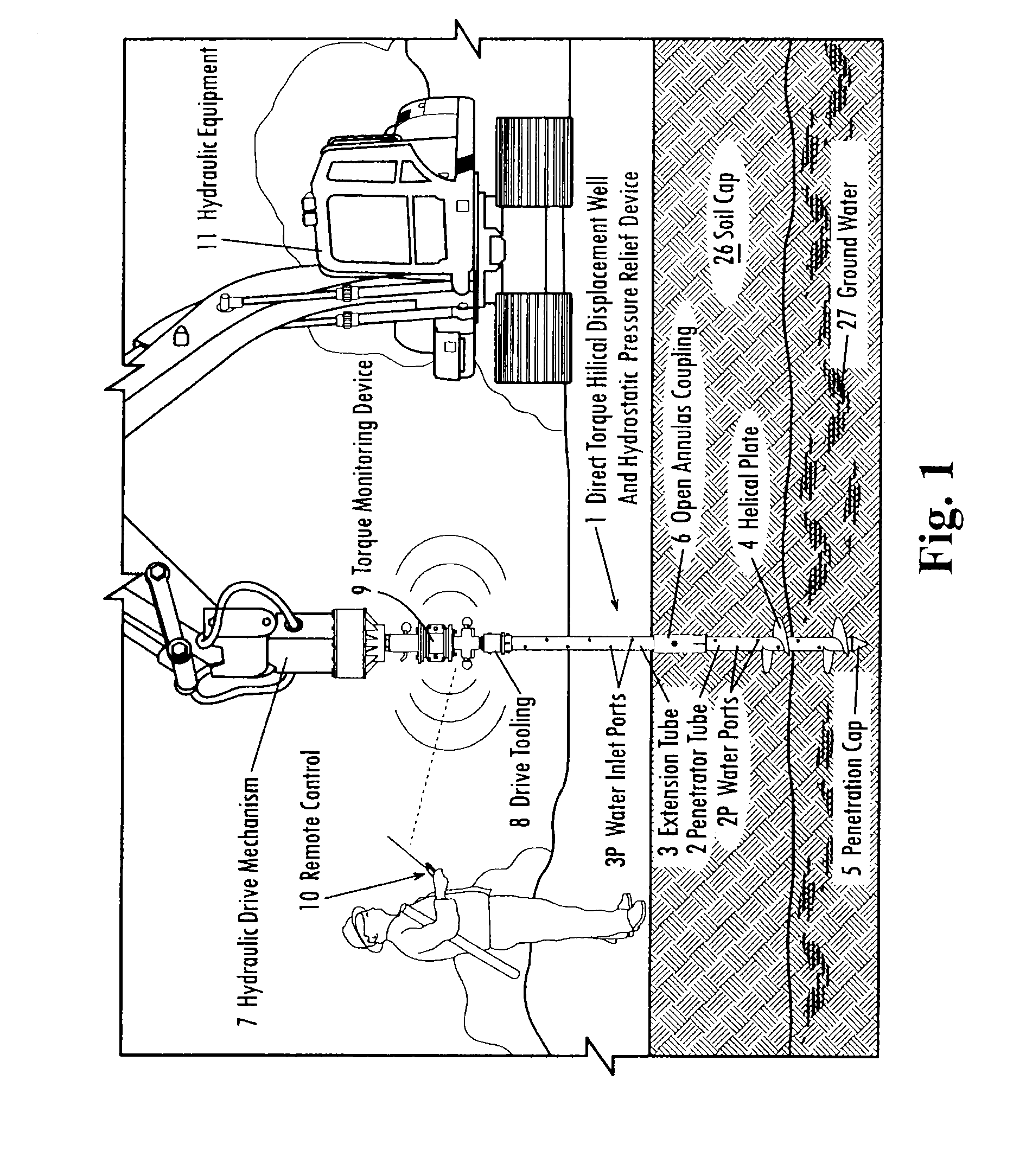
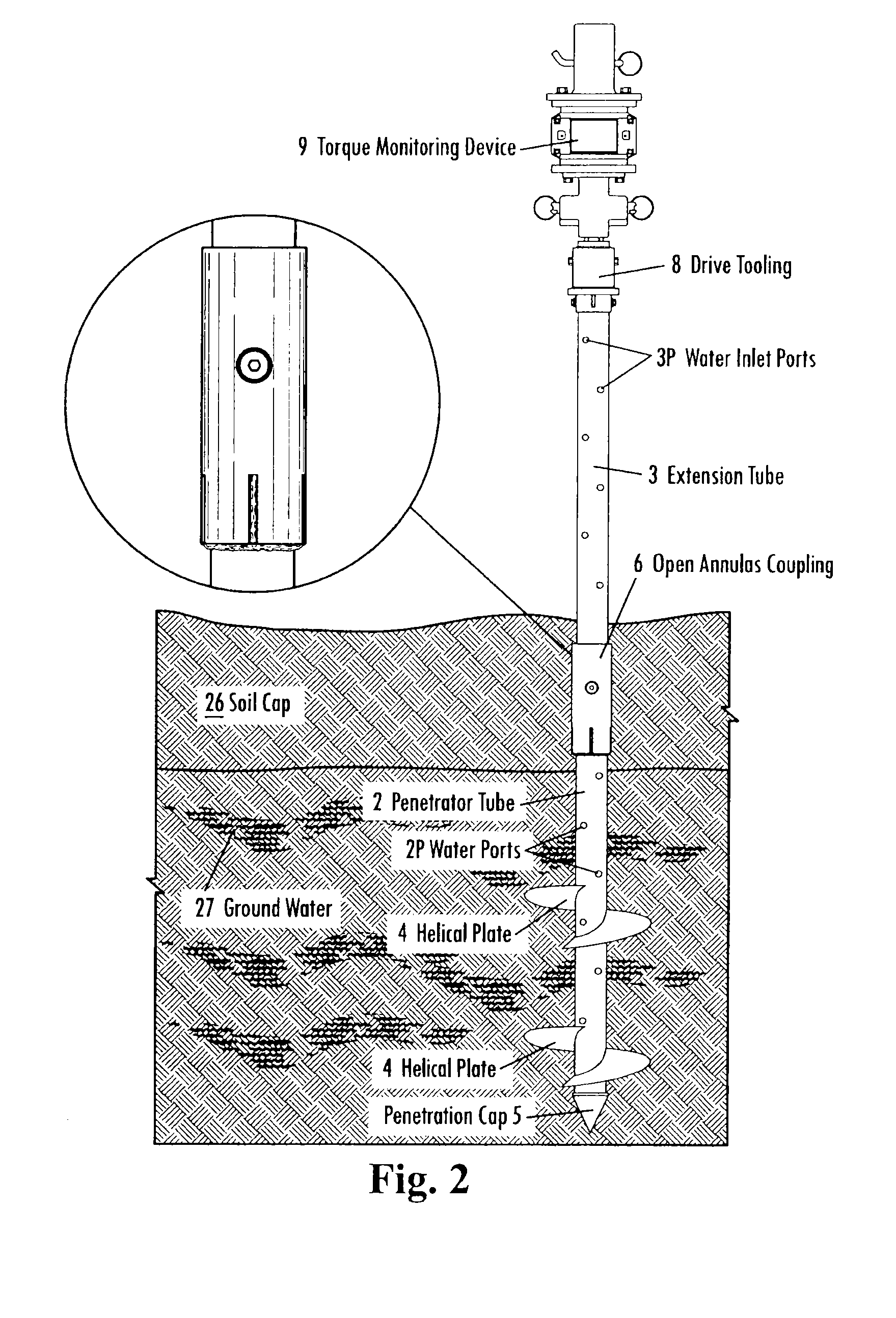
[0072]Referring now in more detail to the drawings, with like numbers referring to the same parts in the several views, FIGS. 1 and 2 illustrate embodiments of the assembled direct torque helical displacement well 1 which may be used as a well or as a hydrostatic pressure relief conduit. FIG. 1 shows how the well is being installed in the ground by an applied direct torque force exerted upon it by a hydraulic drive mechanism 7 to a penetrator tube 2 which is a rectilinear cylindrical tube and is rotated by the hydraulics from the hydraulic installation equipment 11. The hydraulic drive mechanism is considered to be prior art and is available from Eskridge and is identified as an anchor drive.

[0073]The helical displacement well 1 may include a leading external steel conduit penetrator tube 2 that makes the initial penetration in the soil and usually at least one external steel conduit extension tube mounted to the upper end of the leading penetrator tube 2. Helical plates 4 are mount...


PUM


Abstract

A helical displacement well with preassembled segments includes a preassembled shaft-forming penetrator tube including helical plates mounted to its exterior that may be rotated to propel the casing into the ground. A hydraulic drill motor rotates the penetrator tube and as it moves deeper into the ground. Extension tubes may be added to and coupled to the penetrator tube. A hydraulic drill motor is attached to the upper end of the extension tubes in order to continue the rotation of the assembled helical displacement well. The filter screen and the piping are installed concurrently with the addition of the extension tubes at the surface of the ground.

Description


Claims


Application Information

Patent Timeline
Owner QUEEN FRIE A R
Why Eureka
Try Eureka