
Touch display apparatus

a display device and touch technology, applied in the field can solve the problems of higher cost of shielding electrode layers and higher cost of touch display devices, and achieve the effect of low manufacturing cos

Inactive Publication Date: 2014-07-17
HANNSTAR DISPLAY CORPORATION
View PDF11 Cites 15 Cited by
  • Summary
  • Abstract
  • Description
  • Claims
  • Application Information

AI Technical Summary

Benefits of technology

The invention provides a touch display apparatus with a lower manufacture cost. By adding a shielding conductive ring on the cover lens of the touch panel and using a conductive adhesive layer to connect the transparent conductive layer on the display panel and the touch panel, the shielding conductive ring can suppress unwanted electrical effects and prevent noise interference. Additionally, the shielding conductive ring can help release electrostatic charges and reduce manufacture costs.

Problems solved by technology

However, the shielding electrode layer having the metallic ground ring is more costly, and needs to be additionally purchased to be adhered on the touch panel.
Although the above-described solution reduces the interference of the display panel on the touch panel, it makes the cost of the touch display apparatus higher.

Method used


Image

  • Touch display apparatus
  • Touch display apparatus
  • Touch display apparatus

Examples


Embodiment Construction

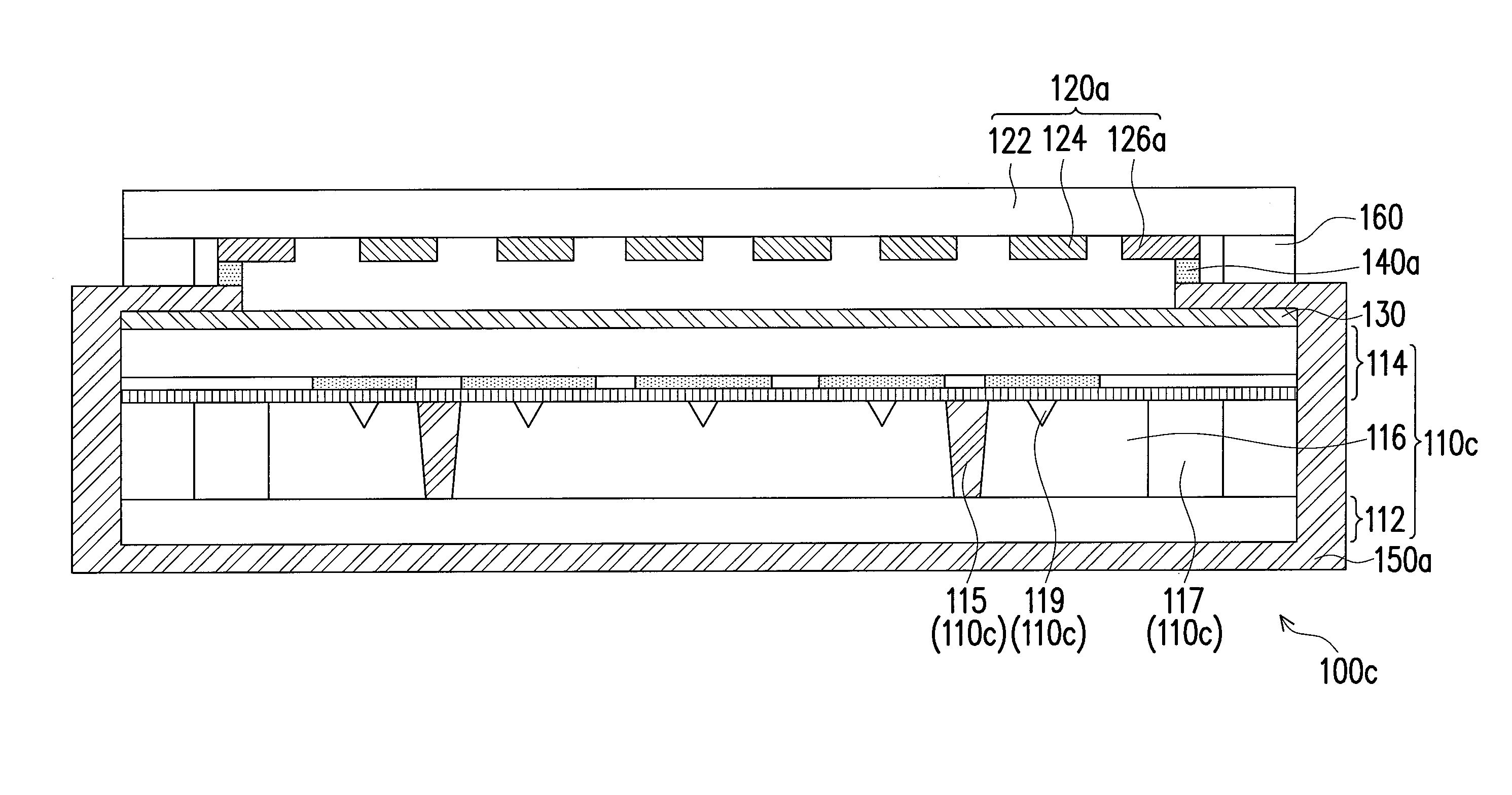
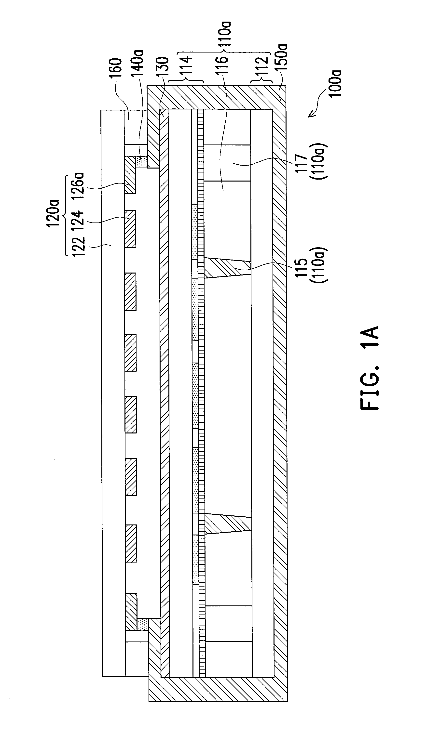
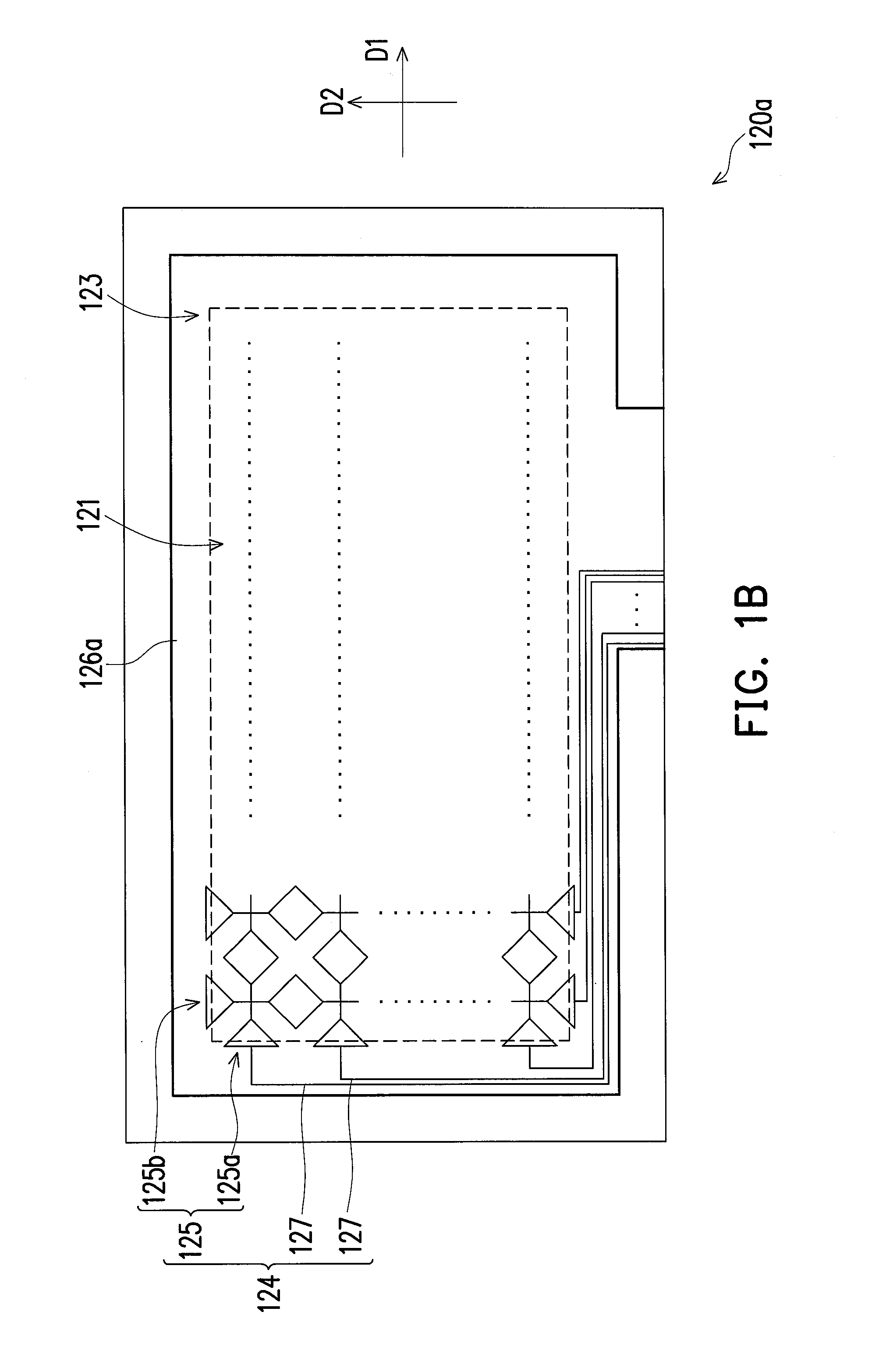
[0026]FIG. 1A is a cross-sectional schematic view of a touch display apparatus according to an embodiment of the invention. FIG. 1B is a bottom schematic view of a touch panel of the touch display apparatus of FIG. 1A. Referring to FIGS. 1A and 1B at the same time, in this embodiment, a touch display apparatus 100a includes a display panel 110a, a touch panel 120a, a transparent conductive layer 130, and a conductive adhesive layer 140a. The touch panel 120a is disposed on the display panel 110a, and includes a cover lens 122, a touch device 124, and a shielding conductive ring 126a. The touch device 124 is disposed on the cover lens 122 and is located between the display panel 110a and the cover lens 122. The shielding conductive ring 126a is disposed on the cover lens 122 and located between the display panel 110a and the cover lens 122, wherein the shielding conductive ring 126a surrounds the touch device 124. The transparent conductive layer 130 is disposed on the display panel ...


PUM


Abstract

A touch display apparatus including a display panel, a touch panel, a transparent conductive layer, and a conductive adhesive layer is provided. The touch panel is disposed on the display panel, and includes a cover lens, a touch device, and a shielding conductive ring. The touch device is disposed on the cover lens and located between the display panel and the cover lens. The shielding conductive ring is disposed on the cover lens and located between the display panel and the cover lens. The shielding conductive ring surrounds the touch device. The transparent conductive layer is disposed on the display panel and located between the display panel and the touch panel. The conductive adhesive layer is disposed between the display panel and the touch panel. The shielding conductive ring is electrically connected with the transparent conductive layer through the conductive adhesive layer.

Description

CROSS-REFERENCE TO RELATED APPLICATION[0001]This application claims the priority benefit of China application serial no. 201310011766.5, filed on Jan. 11, 2013. The entirety of the above-mentioned patent application is hereby incorporated by reference herein and made a part of this specification.BACKGROUND OF THE INVENTION[0002]1. Field of the Invention[0003]The invention relates to a touch display apparatus, and particularly relates to a touch display apparatus having a shielding effect.[0004]2. Description of Related Art[0005]With increasing progress towards display technologies, displays facilitate our daily lives, and the demands for light and compact displays contribute to development of flat panel displays (FPDs) as mainstream displays. Recently, all type of electronic products are developed toward easy operation, small volume, and large screen, and the demands of the volume and the screen size in the portable products are particularly stringent. Therefore, many electronic pro...

Claims


Application Information

Patent Timeline
Patent Type & Authority Applications(United States)
IPC IPC(8): G06F3/041
CPCG06F3/0412G06F3/0443G06F3/0446G06F2203/04107G06F3/041
Inventor WU, HSU-HOYU, CHIA-HUALIU, HSUAN-CHENJUAN, YI-CHUNGYEH, CHANG-CHING
Owner HANNSTAR DISPLAY CORPORATION
Learn More