Method and device for determining values which are suitable for distortion correction of an image, and for distortion correction of an image

a technology of image distortion correction and value determination, applied in image enhancement, instruments, computing, etc., can solve the problems of large memory requirement and meet the requirement for a small memory requirement, and achieve the effect of reducing memory requirement and facilitating distortion correction very quickly

Active Publication Date: 2014-07-17
ROBERT BOSCH GMBH
View PDF7 Cites 4 Cited by
  • Summary
  • Abstract
  • Description
  • Claims
  • Application Information

AI Technical Summary

Benefits of technology

[0011]In a step of storing, the suitable values for distortion correction of the image may be stored in a memory of a device for distortion correction of the image. Thus, the values for the distortion correction may be accessed directly during the distortion correction without the need for redetermining the values for each distorted image to be corrected. If the distortion correction is carried out pixel for pixel, for a pixel to be instantaneously corrected, a shift vector corresponding to the pixel may be determined from the values for the distortion correction and used for shifting the pixel. Individual values for the distortion correction may be used for determining shift vectors of different pixels. This reduces the memory requirement compared to a method in which the shift vectors are stored. Since the shift vectors may be computed very rapidly from the values for the distortion correction, the distortion correction may be carried out very quickly.
[0012]In addition, the step of storing may include a step of compressing the suitable values for distortion correction of the image. The memory occupied by the values for the distortion correction may thus be further reduced. Decompression is carried out to use the values for the distortion correction.

Problems solved by technology

There is a very large memory requirement when the values of the vector field are stored in a memory of a device for distortion correction of the distorted image.
Such a method thus differs from real time-capable methods currently used, which, although they meet the requirement of a computation rule which is as simple as possible, require a very large amount of memory space, and therefore specifically do not meet the requirement for a small memory requirement.

Method used


Image

  • Method and device for determining values which are suitable for distortion correction of an image, and for distortion correction of an image
  • Method and device for determining values which are suitable for distortion correction of an image, and for distortion correction of an image
  • Method and device for determining values which are suitable for distortion correction of an image, and for distortion correction of an image

Examples


Embodiment Construction

[0032]In the following description of preferred exemplary embodiments of the present invention, the same or similar reference numerals are used for the functionally equivalent elements illustrated in the various figures, so that a repeated description of these elements is dispensed with.

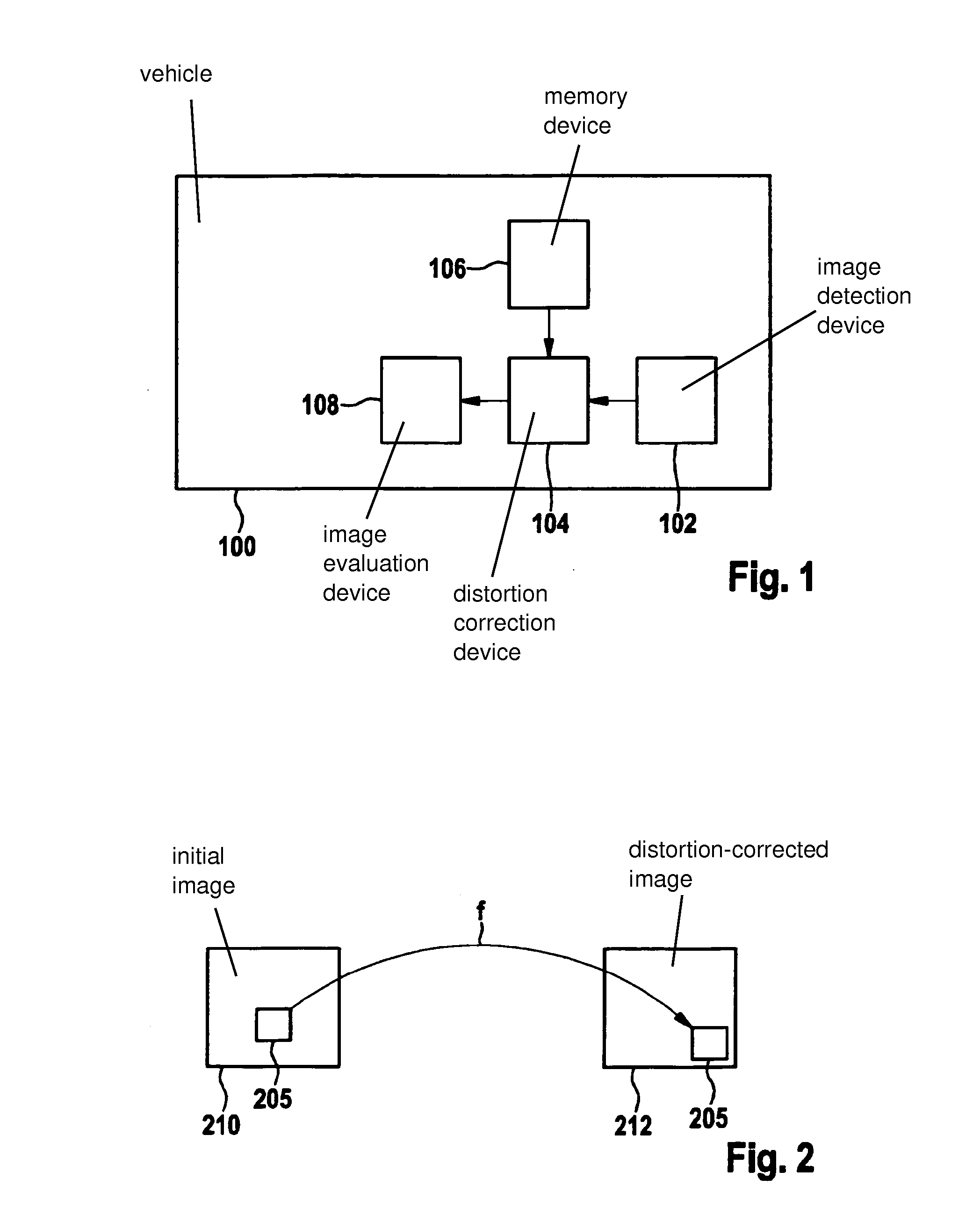
[0033]FIG. 1 shows a vehicle 100 having an image detection device 102, a distortion correction device 104, a memory device 106, and an image evaluation device 108 according to one exemplary embodiment of the present invention. Image detection device 102 may be a camera which is designed to monitor the surroundings or an interior of vehicle 100. Image detection device 102 is designed to detect images in a time sequence and provide the image information in the form of pixels to distortion correction device 104 via an interface. Distortion correction device 104 is designed to correct distortion of the image received from image detection device 102, and to provide same as a distortion-corrected image to ...


PUM


Abstract

A method for determining values which are suitable for distortion correction of an image, including the following steps: a step of splitting a vector field, which is suitable for distortion correction of the image, into a sum of vector products, and a step of determining terms of the vector products as suitable values for distortion correction of the image.

Description

FIELD OF THE INVENTION[0001]The present invention relates to a method for determining values which are suitable for distortion correction of an image, a method for distortion correction of an image composed of multiple pixels, a corresponding device, and a corresponding computer program product.BACKGROUND INFORMATION[0002]International Published Patent Appln. No. WO 02 / 078346 describes a method in which a source image that is distorted by camera optics is converted into a distortion-corrected target image with the aid of a tabular imaging rule. This conversion occurs directly during the reading out from the image sensor, and in real time. No, one, or multiple target pixels is / are assigned to each source pixel of the source image.SUMMARY[0003]Against this background, the present invention presents a method for determining values which are suitable for distortion correction of an image, a method for distortion correction of an image composed of multiple pixels, a device which uses at ...

Claims


Application Information

Patent Timeline
Patent Type & Authority Applications(United States)
IPC IPC(8): G06T5/00G06K9/52
CPCG06K9/52G06T5/006
Inventor WEBER, STEFAN
Owner ROBERT BOSCH GMBH
Why Eureka
Try Eureka