Sensor positionig with non-dispersive guided waves for pipeline corrosion monitoring

a technology of positioning and guided waves, applied in the direction of instruments, heat measurement, specific gravity measurement, etc., can solve the problems of time-consuming and difficult to provide precise longitudinal alignmen

Active Publication Date: 2014-07-24
BAKER HUGHES INC
View PDF8 Cites 17 Cited by
  • Summary
  • Abstract
  • Description
  • Claims
  • Application Information

AI Technical Summary

Problems solved by technology

Providing precise longitudinal alignment could be difficult and time consuming.

Method used


Image

  • Sensor positionig with non-dispersive guided waves for pipeline corrosion monitoring
  • Sensor positionig with non-dispersive guided waves for pipeline corrosion monitoring
  • Sensor positionig with non-dispersive guided waves for pipeline corrosion monitoring

Examples


example embodiment (

[0015]Example embodiment(s) that incorporate one or more aspects of the present invention are described and illustrated in the drawings. These illustrated examples are not intended to be a limitation on the present invention. For example, one or more aspects of the present invention can be utilized in other embodiments and even other types of devices. Moreover, certain terminology is used herein for convenience only and is not to be taken as a limitation on the present invention. Still further, in the drawings, the same reference numerals are employed for designating the same elements.

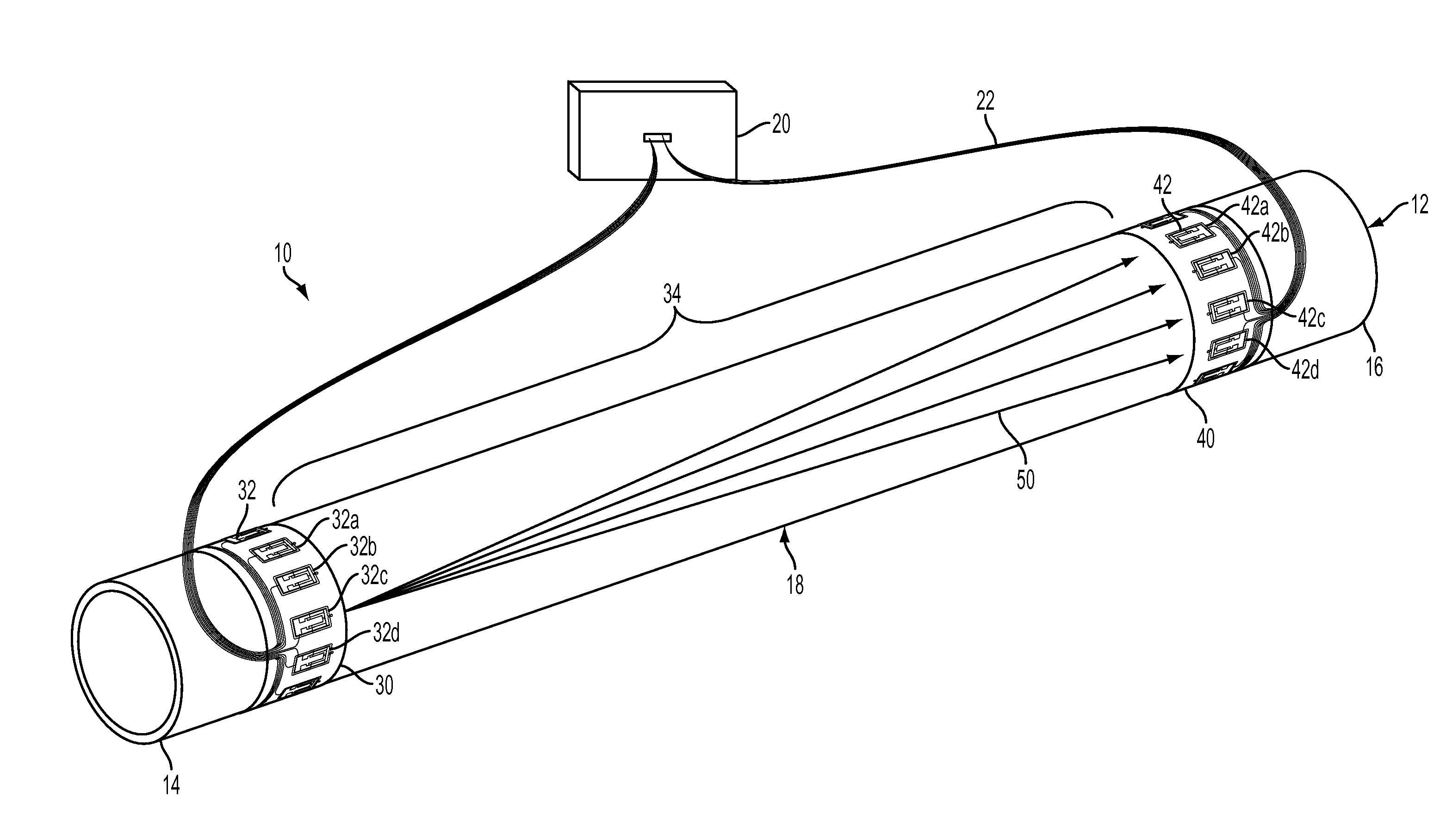
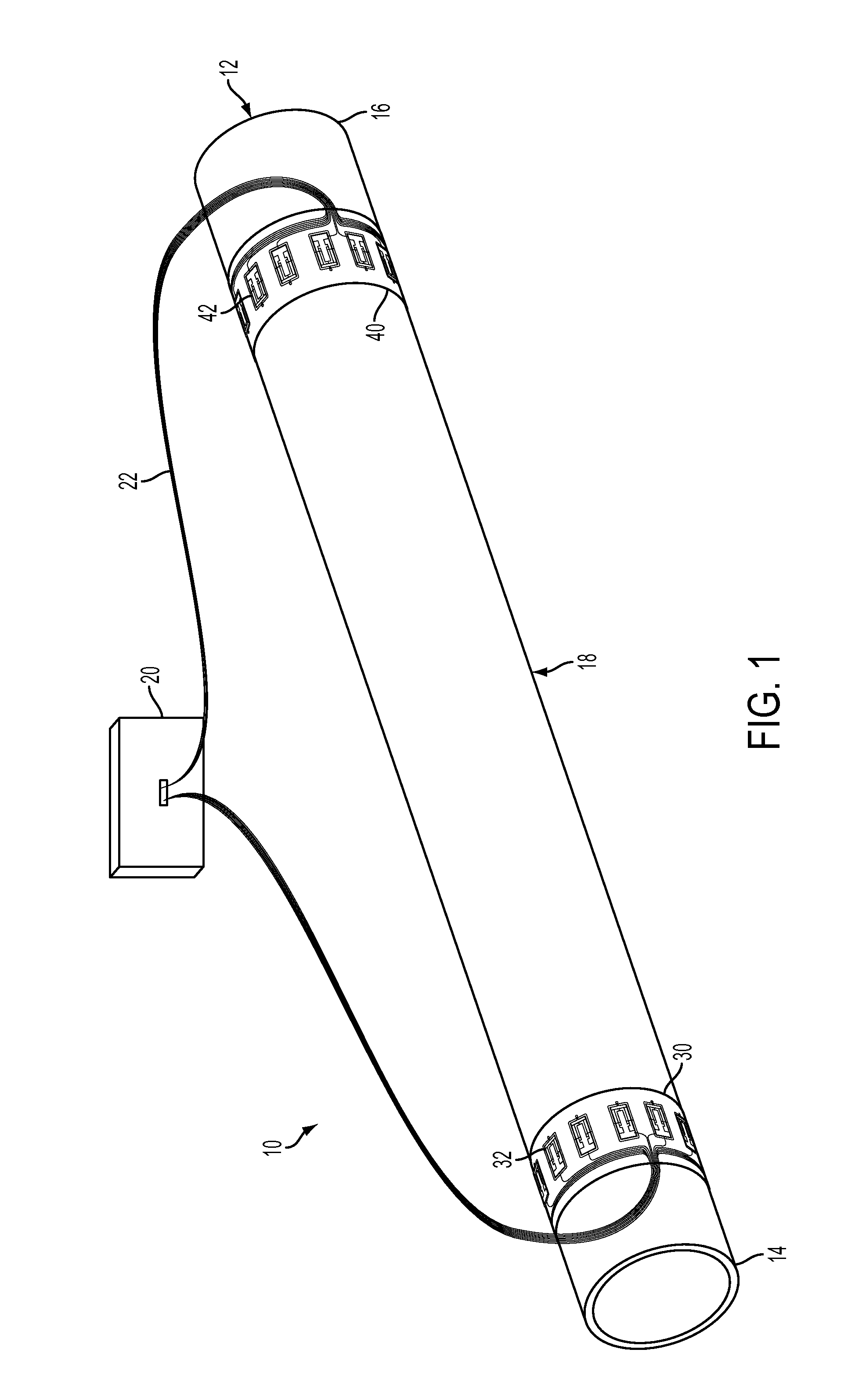
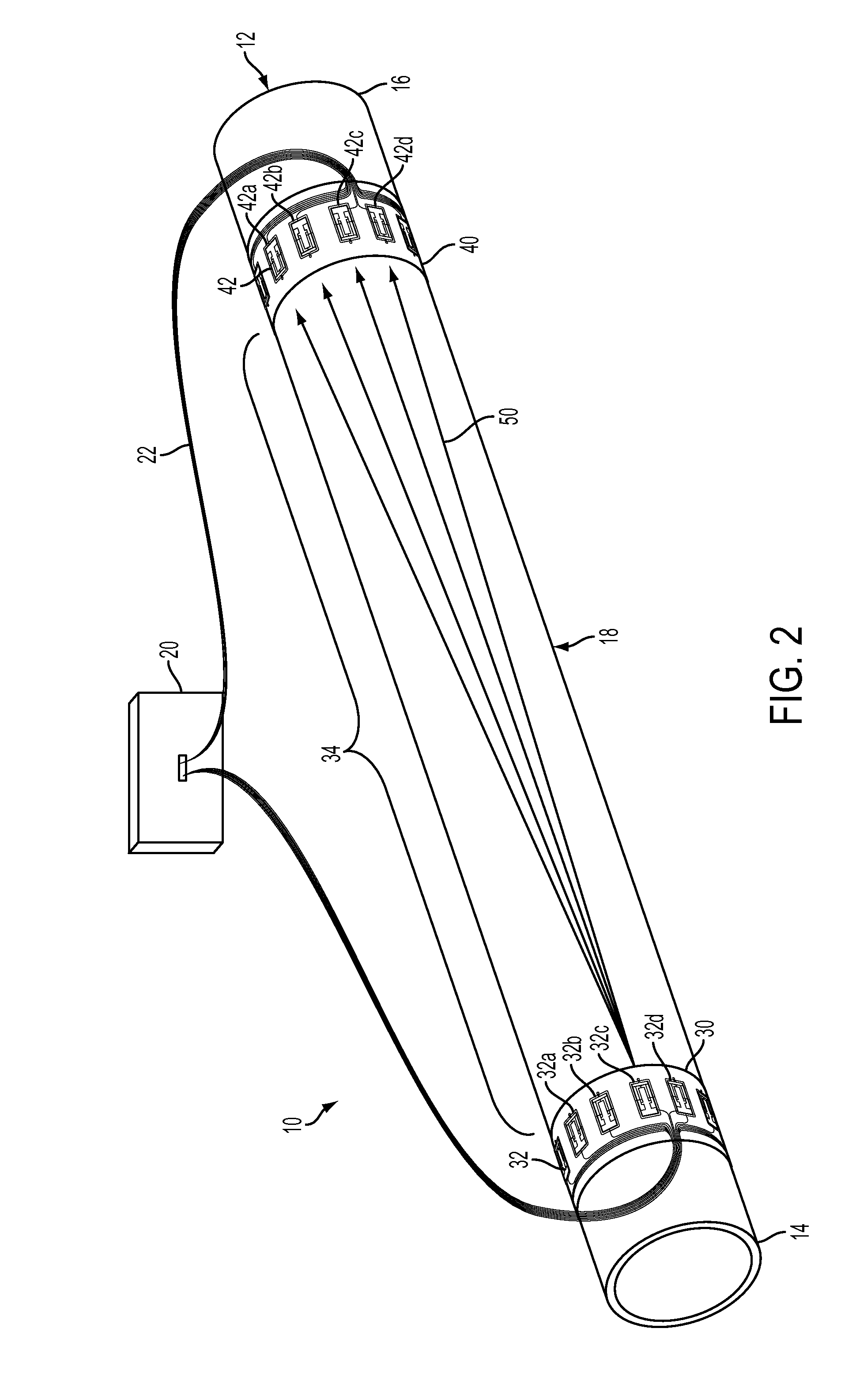
[0016]FIG. 1 illustrates a perspective view of an example ultrasonic sensor assembly 10 according to one aspect of the invention. In short summary, the ultrasonic sensor assembly 10 includes a controller 20 in operative association with a first transducer ring 30 and a second transducer ring 40. The first and second transducer rings 30, 40 can transmit ultrasonic waves into a pipe 12 for testing the pi...


PUM

PropertyMeasurementUnit
lengthaaaaaaaaaa
time of flightaaaaaaaaaa
separation distanceaaaaaaaaaa

Abstract

An ultrasonic sensor assembly for testing a pipe includes a first and second transducer rings attached to the pipe and spaced apart along a length of the pipe. The first transducer ring includes a plurality of transmitters for transmitting a wave, such as a non-dispersive guided wave. The first transducer ring transmits the wave along the pipe. The second transducer ring includes a plurality of receivers for receiving the wave. A relative position of the first transducer ring with respect to a circumferential position of the second transducer ring is determined based on characteristics of the wave received by the second transducer ring. A method of positioning the ultrasonic sensor assembly on the pipe is also provided.

Description

BACKGROUND OF THE INVENTION[0001]1. Field of the Invention[0002]The present invention relates generally to ultrasonic sensor assemblies, and more particularly, to aligning an ultrasonic sensor assembly on a pipe.[0003]2. Discussion of the Prior Art[0004]Ultrasonic sensor assemblies are known and used in many different applications. Ultrasonic sensor assemblies are used, for example, to inspect a pipe and detect / identify at least one characteristic of the pipe, such as corrosion, voids, inclusions, length, thickness, etc. To accurately determine the location of these characteristics of the pipe, a relative position of a first transducer ring with respect to a second transducer ring should be known. In the past, the first transducer ring would be precisely longitudinally aligned with the second transducer ring, such that circumferential locations of transmitters in the first transducer ring would match circumferential locations of receivers in the second transducer ring. Providing pre...

Claims


Application Information

Patent Timeline
Patent Type & Authority Applications(United States)
IPC IPC(8): G01N29/22G01H5/00
CPCG01H5/00G01N29/223G01N29/041G01N29/07G01N2291/0425G01N2291/106G01N2291/2634Y10T29/49764G01N29/04G01N29/22G01N2291/02854G01N2291/0289
Inventor LUO, WEIBARSHINGER, JAMES NORMANMISHRA, DEBASISHRAMMOHAN, ANUSHA
Owner BAKER HUGHES INC
Why Eureka
Try Eureka