Wire harness
- Summary
- Abstract
- Description
- Claims
- Application Information
AI Technical Summary
Benefits of technology
Problems solved by technology
Method used
Image

Examples
first embodiment
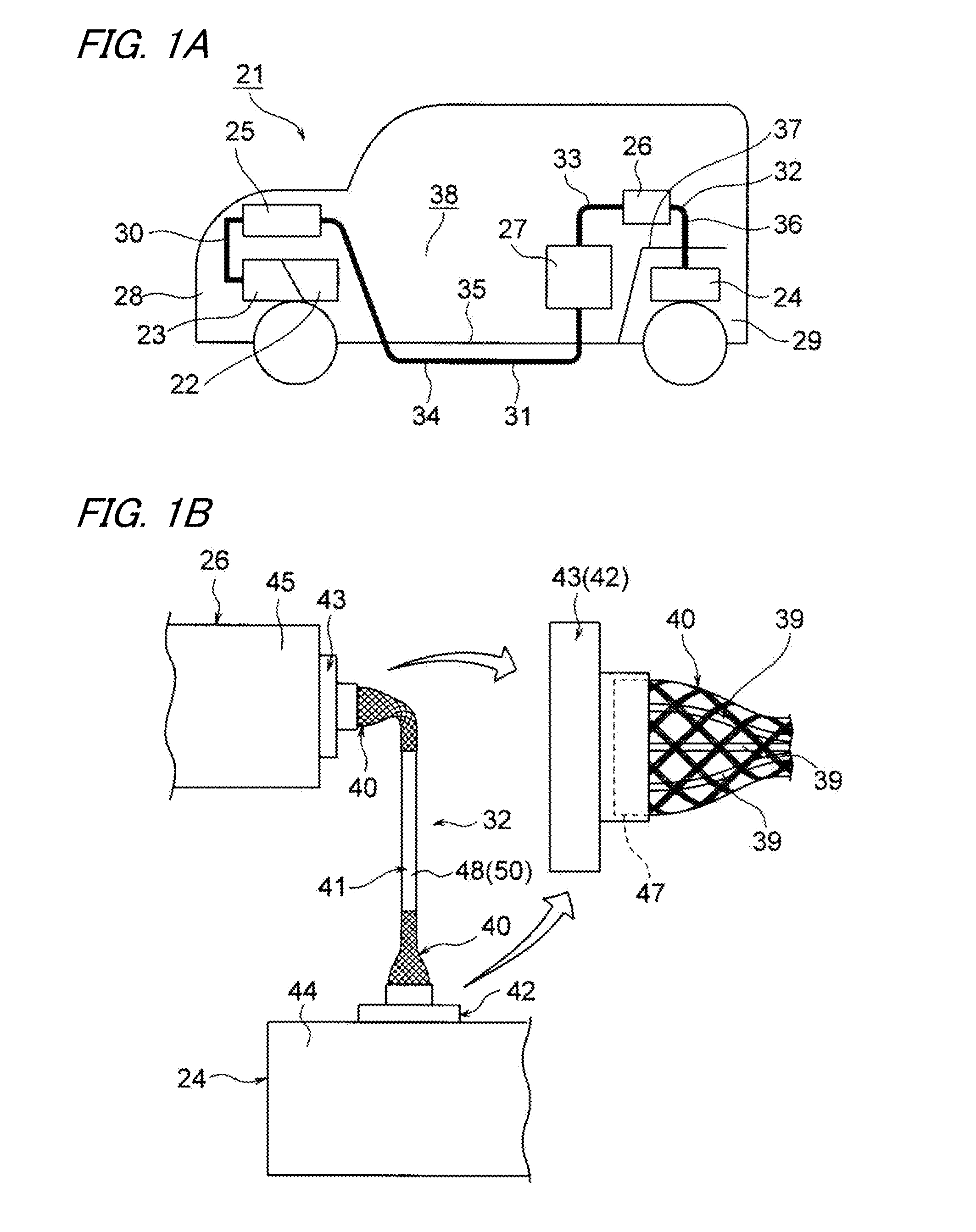
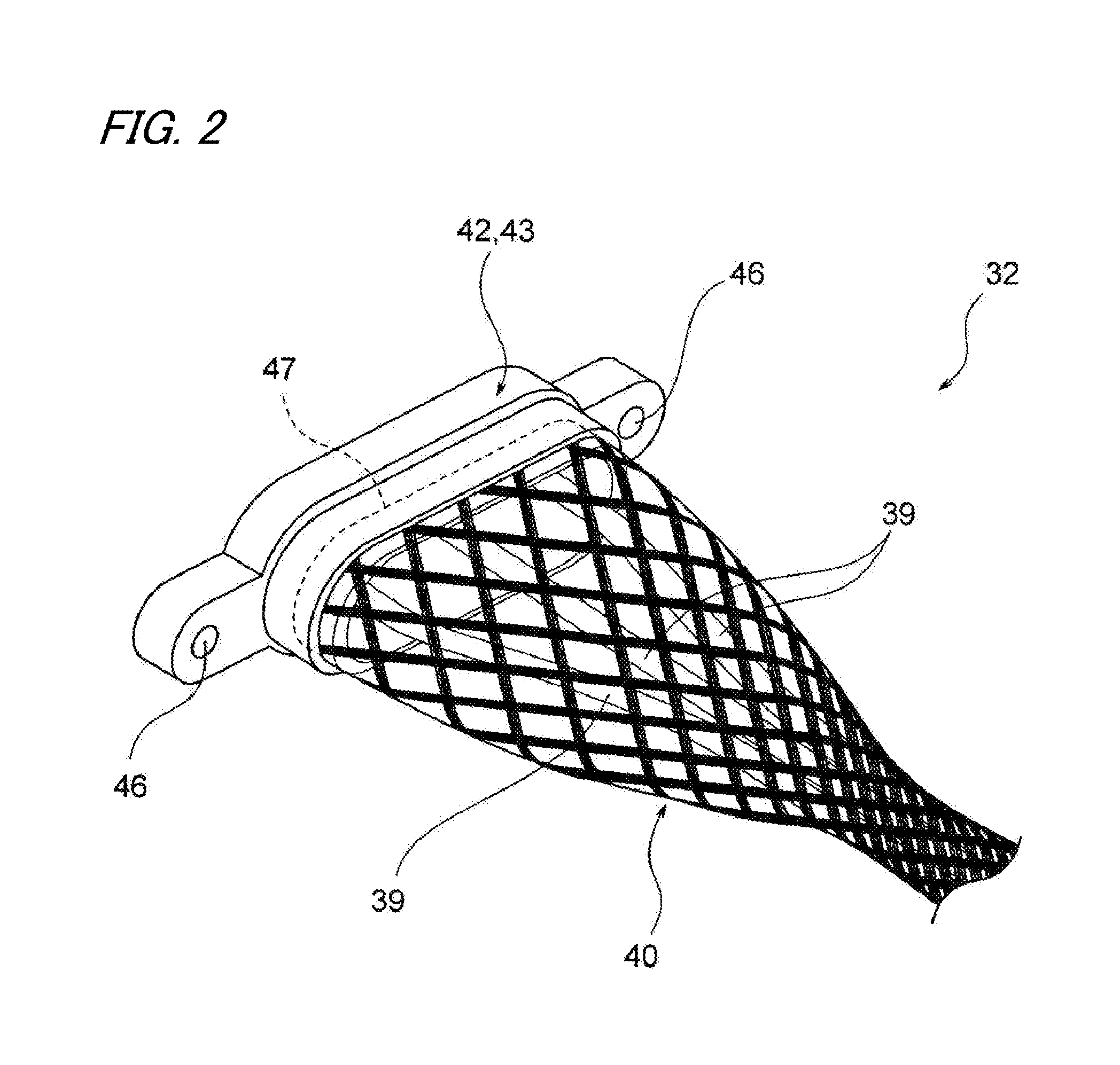
[0028]A first embodiment is hereunder described by reference to the drawings. FIGS. 1A and 1B are drawings showing a wire harness of the embodiment of the invention. FIG. 2 is an enlarged perspective view showing a shielding structure of a wire harness terminal, and FIGS. 3A and 3B are drawings showing a sheathing member.
[0029]In the embodiment, explanations are given with an example in which the wire harness is adopted for a hybrid automobile (it can also be an electric vehicle).
[0030]In FIG. 1A, reference symbol 21 designates a hybrid automobile. The hybrid automatable 21 is a vehicle that is driven by combined use of an engine 22, a front motor unit 23, a rear motor unit 24. The front motor unit 23 is supplied with electric power from a battery 27 (a battery pack or an assembled battery) by way of a front inverter unit 25, and the rear motor unit 24 is supplied with electric power from the battery 27 by way of a rear inverter unit 26. The engine 22, the front motor unit 23, and t...
second embodiment
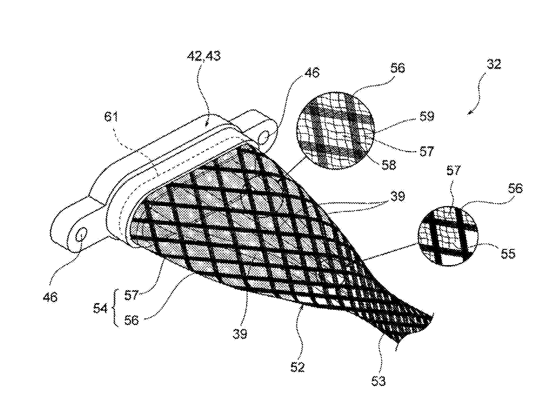
[0053]A second embodiment is hereunder described by reference to the drawings. FIG. 4 is an enlarged perspective view showing a shielding structure of another embodiment. FIGS. 5A to 5C are explanatory views of the shielding structure of FIG. 4 in an unbraided state. The constituent members that are the same as those described in connection with the first embodiment are assigned the same reference numerals, and their detailed explanations are omitted. Reference is made to FIG. 1 in connection with the second embodiment.
[0054]In FIG. 1B and 4, the wire harness 32 routed in the same manner as described in connection with the first embodiment is made up of the three high voltage cables 39 (electrically conducting paths); a braided wire 52 that collectively shields the three high voltage cables 39; a sheathing member 41 disposed outside the main body of the braided wire 52; the motor-side connector portion 42 to be provided at one side of the three high voltage cables 39; and the invert...
third embodiment
[0066]A third embodiment is hereunder described by reference to the drawings. FIG. 6 is an enlarged perspective view of a shielding structure that is to be still another embodiment. The constituent members that are the same as those described in connection with the first and second embodiments are assigned the same reference numerals, and their detailed explanations are omitted.
[0067]In FIG. 6, the shielding structure of the third embodiment differs from its counterparts described in connection with the first and second embodiments in use of a braided wire 62. A braided wire formed from strands of extra fine conductive element wires made of conductive non-metallic fibers that are lighter than metallic fibers is used as the braided wire 62 in the same way as in the first and second embodiments. In the braided wire 62, the element wires are formed from; for instance, non-metallic fibers that are lighter than metallic fibers per unit length. Consequently, the braided wire becomes light...
PUM
 Abstract
Description
Claims
Application Information
 - Generate Ideas
- Intellectual Property
- Life Sciences
- Materials
- Tech Scout
- Unparalleled Data Quality
- Higher Quality Content
- 60% Fewer Hallucinations
Browse by: Latest US Patents, China's latest patents, Technical Efficacy Thesaurus, Application Domain, Technology Topic, Popular Technical Reports.
© 2025 PatSnap. All rights reserved.Legal|Privacy policy|Modern Slavery Act Transparency Statement|Sitemap|About US| Contact US: help@patsnap.com