
Cargo Theft Prevention System and Method

a theft prevention and cargo technology, applied in the field of cargo theft prevention system and method, can solve problems such as failure to solve, and achieve the effect of reducing and eliminating cargo th

Inactive Publication Date: 2014-07-24
INTELLIGENT TECH INT
View PDF6 Cites 22 Cited by
  • Summary
  • Abstract
  • Description
  • Claims
  • Application Information

AI Technical Summary

Benefits of technology

[0020]It is an object of the present invention to provide new and improved systems for reducing and eliminating the theft of cargo that resides in truck trailers, of the trailer with the cargo or of the tractor and cargo containing trailer.
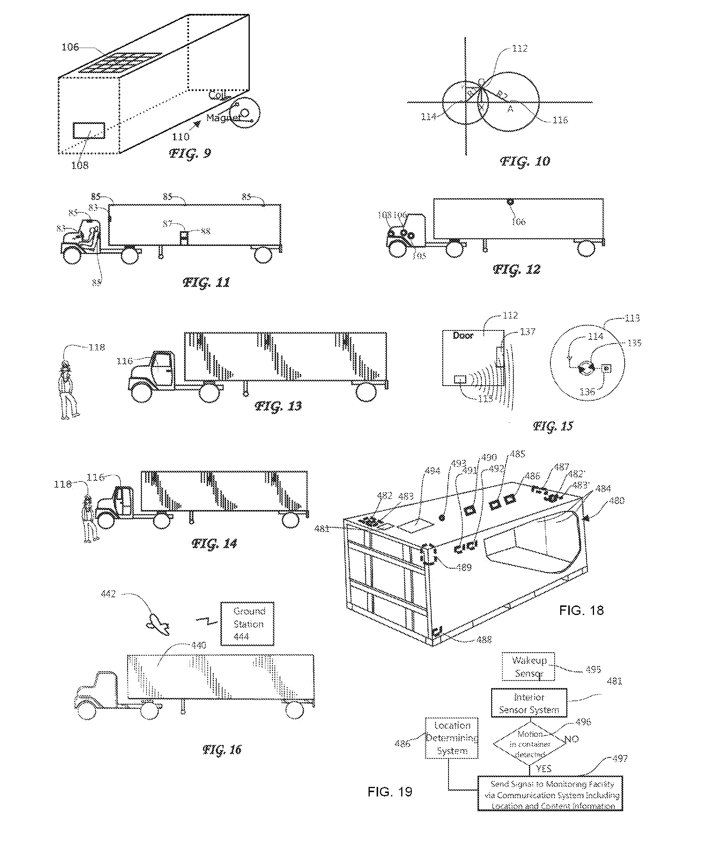
[0023]To efficiently manage power yet provide suitable protection, the sensor system may include an initiation device for periodically initiating the sensor system to obtain information about the vehicle or its contents. A wakeup sensor system detects the occurrence of an internal or external event, or the absence of an event for a time period, requiring a change in the frequency of monitoring of the trailer and transmitting messages. The initiation device is coupled to the wakeup sensor system and changes the rate at which it initiates the sensor system to obtain information about the trailer in response to the detected occurrence of an internal or external event by the wakeup sensor system. In particular, when the trailer is not moving indicating that it is parked, the transmission frequency is substantially increased so that the remote site that is receiving the information can detect that a theft may be in process if the transmissions cease without a message from the driver that he has returned to the tractor. Such a driver returned message can be initiated by the sensing of a tag, smart card, smart phone or other equivalent device carried by the driver or by a sensing of an identifiable biometric signature by a sensor within or associated with the tractor or by a cell phone or other driver initiated communication.

Problems solved by technology

This solution is destined to fail as thieves become aware of this approach and move to defeat it.

Method used


Image

  • Cargo Theft Prevention System and Method
  • Cargo Theft Prevention System and Method
  • Cargo Theft Prevention System and Method

Examples


examples

Simple Cargo Movement

[0304]The simplest method of implementing a portion of the invention is to use a cell phone, PDA or other portable device with the appropriate application. Cell phones, or smartphones, that are now sold contain a GPS-based location system as do many other devices such as PDAs, iPADs or equivalents. Such a system along with minimal additional apparatus can be used to practice the teachings disclosed herein. In this case, the cell phone, PDA or similar portable device can be mounted through a snap-in attachment system, for example, wherein one or more portable devices can be firmly attached to the container and perhaps inside the tractor. The device(s) can at that point, for example, obtain an ID number from the container through a variety of methods such as a wireless RFID, SAW or hardwired based system. It can also connect to a chosen remote site using SMS text messaging or similar system. Since the portable device would only operate on a low duty cycle, the bat...


PUM


Abstract

Arrangement and method for monitoring a structure at a fixed location, e.g., a house, parked boat or parked airplane, includes a monitoring or sensor system arranged to obtain information about the structure, an exterior of the structure and / or an interior of the structure different than the location of the structure, and a communication system coupled to the sensor system and being provided with a location of the structure. The communication system transmits the information about the structure obtained by the sensor system and the location of the structure to a remote facility. The remote facility can therefore monitor the structure, and take steps to ensure the integrity of the reservoir and the fluid therein. To enable wireless and powerless monitoring, a power source independent of a power grid extending outside of the trailer may be provided to supply power to the sensor system and the communications unit.

Description

CROSS REFERENCE TO RELATED APPLICATIONS[0001]This application is a continuation of International Application No. PCT / US2012 / 029079 filed Mar. 14, 2012 which claims priority of U.S. provisional patent application Ser. Nos. 61 / 452,418 filed Mar. 14, 2011, now expired, 61 / 508,822 filed Jul. 18, 2011, now expired, and 61 / 584,642 filed Jan. 9, 2012, now expired, all of which are incorporated by reference herein.FIELD OF THE INVENTION[0002]The present invention relates to arrangements and methods for monitoring fixed structures such as buildings and vacations homes, for break-ins, fire, smoke, water, pollution, etc.BACKGROUND OF THE INVENTION[0003]The theft of cargo in the United States has been reported by the FBI (http: / / www.fbi.gov / news / stories / 2010 / november / cargo—111210 / cargo—111210) as being approximately $30 Billion annually in terms of the actual cargo value and may be as much as ten times that amount if all costs are take into account such as disruptions in the supply chain. C. H....

Claims


Application Information

Patent Timeline
Patent Type & Authority Applications(United States)
IPC IPC(8): B60T1/00B60T7/16G08B13/00B60T1/06
CPCB60T1/005B60T7/16G08B13/1436G08B13/19647G08B13/2417B60T1/067G08B13/00H04K3/226H04K3/88H04K2203/16Y10T70/65H04K3/222H04K2203/22G01S13/04G08B13/1427
Inventor BREED, DAVID S.
Owner INTELLIGENT TECH INT
Learn More