Imaging Apparatus

a technology of imaging apparatus and focusing device, which is applied in the direction of instruments, television systems, color signal processing circuits, etc., can solve the problems of reducing the resolution of the photographic subject in the vertical direction, the setting value may not be suitable for focus detection, and the failure to successfully complete focus detection, so as to prevent the resolution in the vertical direction from deteriorating, the effect of reducing the amount of noise and high accuracy of focus detection processing

Active Publication Date: 2014-07-24
CANON KK
View PDF3 Cites 23 Cited by
  • Summary
  • Abstract
  • Description
  • Claims
  • Application Information

AI Technical Summary

Benefits of technology

[0008]The present invention is directed to a technique capable of controlling a line addition range of a focus detection area according to shooting conditions in a focus detection to be performed with an image sensor including a photoelectric conversion portion that has a pupil-d

Problems solved by technology

Therefore, if only the shooting conditions are taken into consideration in determining an exposure setting value to control the image sensor, the setting value may be inappropriate for the focus detection.
Further, in a case where an operator arbitrarily switches or changes the

Method used


Image

  • Imaging Apparatus
  • Imaging Apparatus
  • Imaging Apparatus

Examples


Embodiment Construction

[0025]Various exemplary embodiments, features, and aspects of the invention will be described in detail below with reference to the drawings. In the following drawings, members similar or identical to each other are denoted by the same reference numerals and redundant description thereof will be avoided.

[0026]

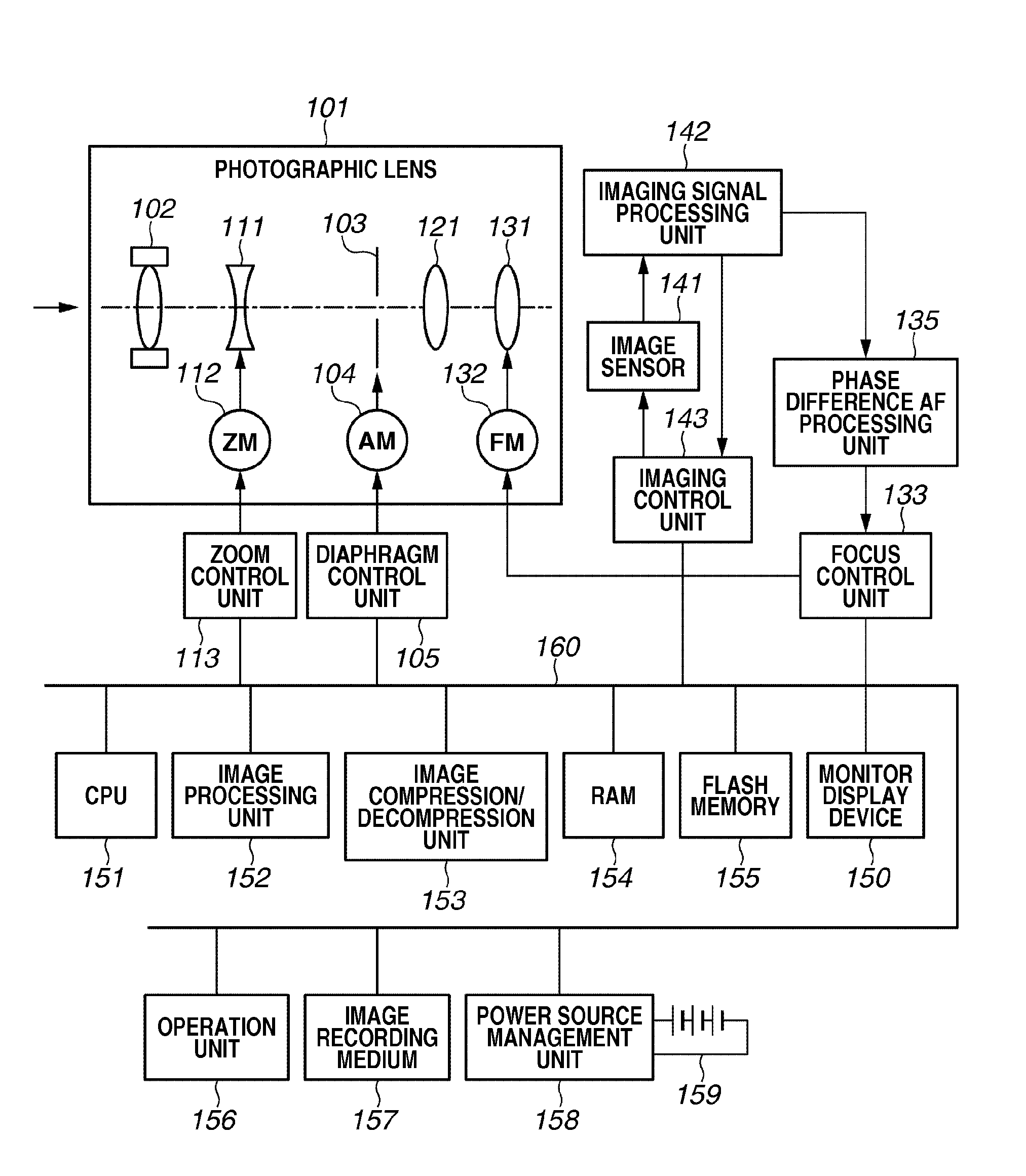
[0027]First, an example configuration of an imaging apparatus according to a first exemplary embodiment is described in detail below with reference to FIG. 1. FIG. 1 is a block diagram illustrating a configuration example of an imaging apparatus 100. The imaging apparatus 100 is a video camera or a digital still camera that is configured to capture an image of a photographic subject and store moving image data or still image data on an appropriate recording medium, such as a tape, a solid memory, an optical disk, or a magnetic disk, although the imaging apparatus 100 is not limited to the above-mentioned examples. The imaging apparatus 100 includes various units that are connec...


PUM


Abstract

An imaging apparatus performs a focus detecting operation with an image sensor including a photoelectric conversion portion that has a pupil-dividing function. The imaging apparatus increases a line addition number according to a target exposure value corresponding to a pixel dynamic range that is variable depending on an exposure setting value. Thus, the imaging apparatus can reduce the amount of noise and can suppress the dispersion of focus detection result. Further, the imaging apparatus changes the line addition number according to a lens diaphragm aperture size, a defocus amount, or a pixel signal reading mode. Thus, the imaging apparatus can secure the resolution in the vertical direction and can prevent the detection accuracy from deteriorating even in a case where a photographic subject is obliquely positioned in a focus detection area.

Description

BACKGROUND OF THE INVENTION[0001]1. Field of the Invention[0002]The present invention relates to an imaging apparatus, such as a digital camera or a video camera.[0003]2. Description of the Related Art[0004]A phase difference detection based auto focus (AF) (hereinafter, referred to as “phase difference AF”) system is employable for an imaging apparatus (e.g., a camera). The phase difference AF imaging apparatus halves the light flux having passed through an exit pupil of a photographic lens and causes a pair of focus detection sensors to receive halved light fluxes. Then, the imaging apparatus obtains a deviation of the photographic lens from an in-focus position (hereinafter, referred to as a defocus amount) by detecting a shift amount between signals output based on the light-receiving amounts, more specifically, by detecting a relative shift amount between the output signals in a light flux division direction (hereinafter, referred to as “image shift amount”).[0005]As discussed ...

Claims


Application Information

Patent Timeline
IPC IPC(8): H04N5/232H04N5/243
CPCH04N5/243H04N5/23212H04N23/672H04N23/76
Inventor OHARA, NAOYUKI
Owner CANON KK
Why Eureka
Try Eureka