Positive feedback ethernet link flow control for promoting lossless ethernet

Active Publication Date: 2014-07-24
AVAGO TECH INT SALES PTE LTD
View PDF8 Cites 23 Cited by
  • Summary
  • Abstract
  • Description
  • Claims
  • Application Information

AI Technical Summary

Benefits of technology

[0006]To address the problems described above, a positive feedba

Problems solved by technology

Unlike other link layer protocols, such as Fibre Channel or Infiniband, the Ethernet link layer protocol did not originally provide a link layer flow control mechanism.
Furthermore, when this occurs, there is no mechanism at the link layer for the node to notify the remote node that it dropped the frame.
The upper layer timeout and retransmission request error recovery solution is undesirable.
Second, the timeout detection and retransmission may involve the host software in the server leading to reduced CPU utilization for the application workload.
Third, even if an offload engine handles the retransmission, power consumption and complexity of the network adapter may be increased.
However, a problem subsequently em

Method used


Image

  • Positive feedback ethernet link flow control for promoting lossless ethernet
  • Positive feedback ethernet link flow control for promoting lossless ethernet
  • Positive feedback ethernet link flow control for promoting lossless ethernet

Examples


Embodiment Construction

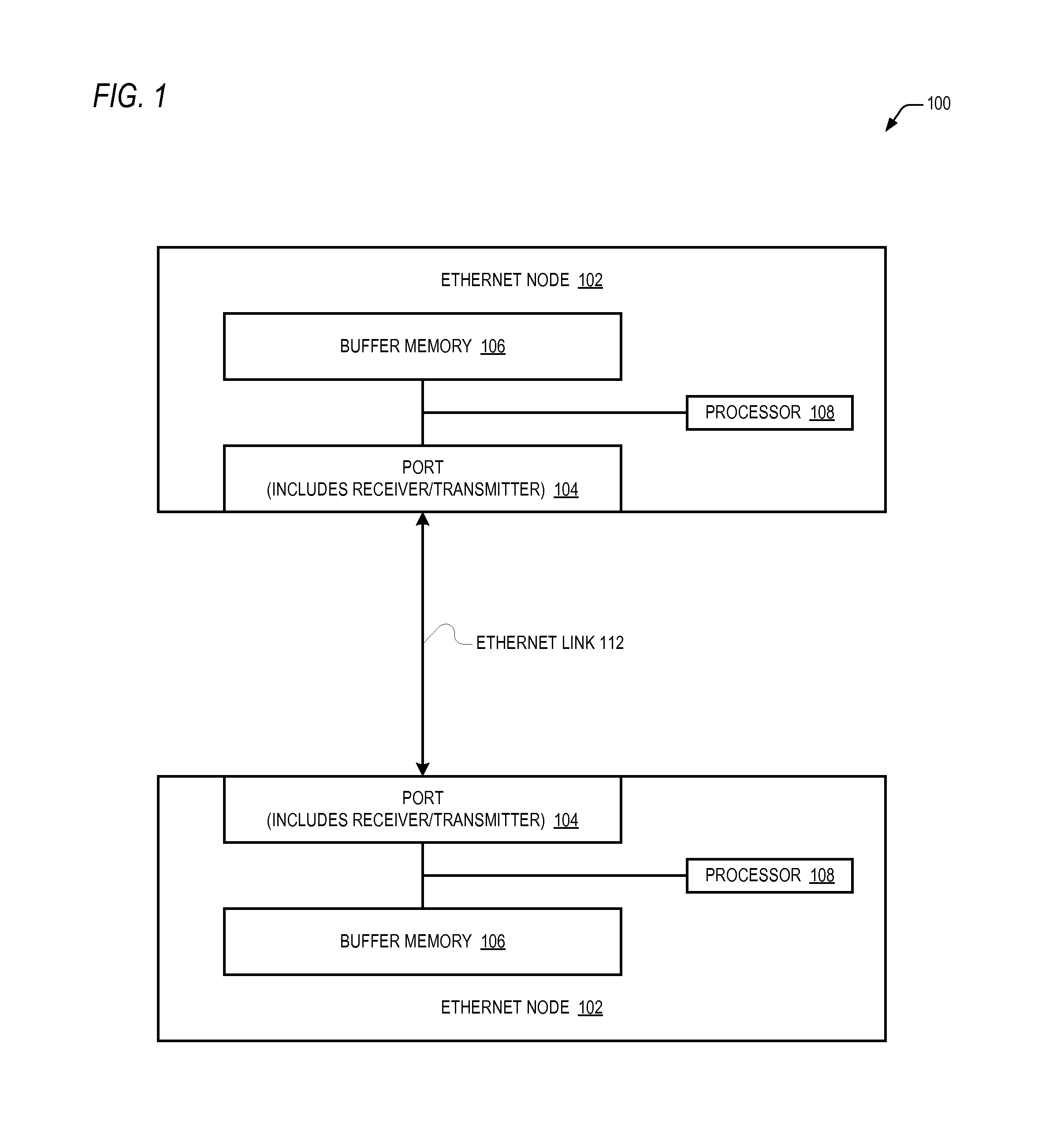
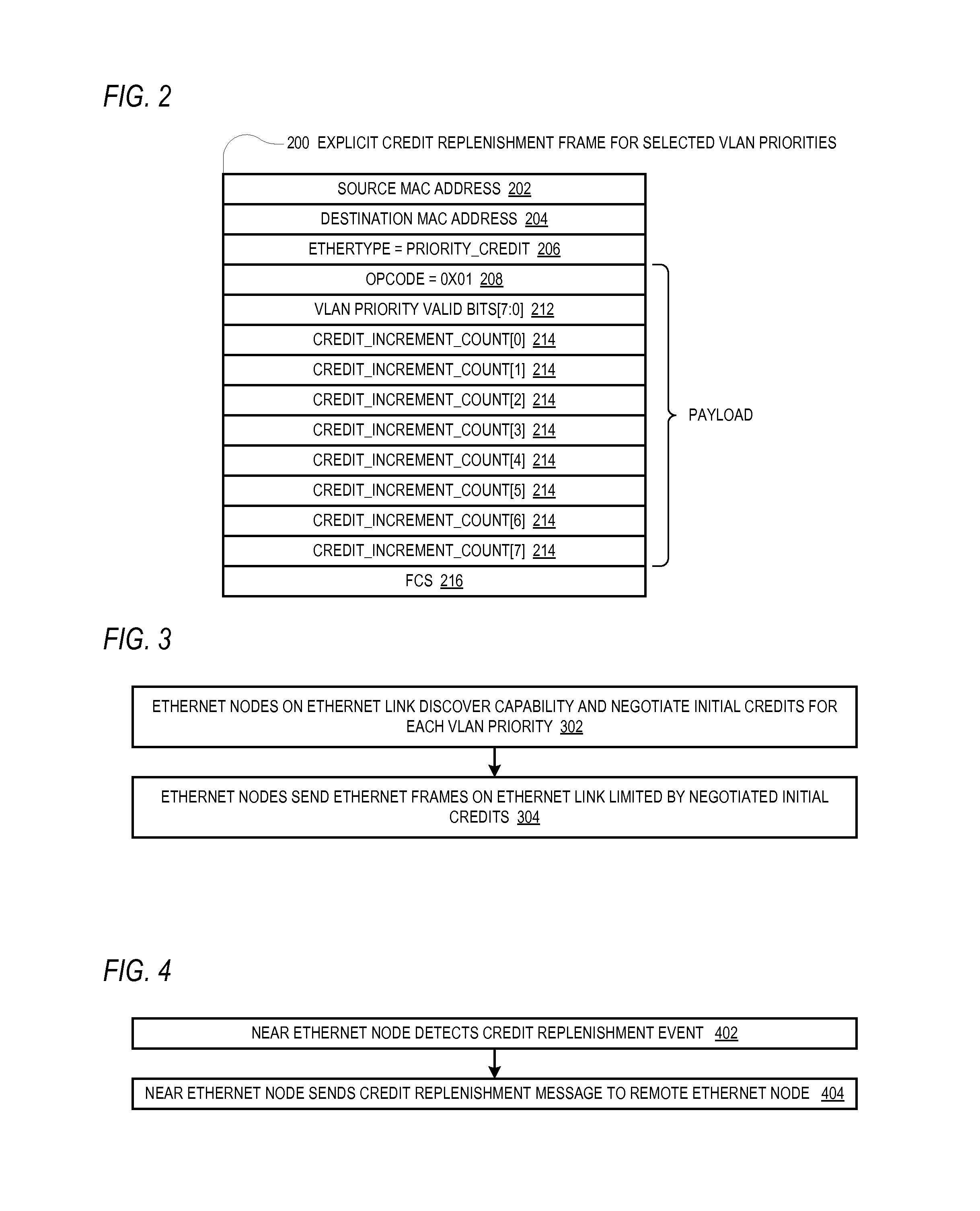
[0017]To address the problems described above, disclosed are embodiments of a positive feedback control system for controlling the flow of Ethernet frames on an Ethernet link between two Ethernet nodes. According to the positive feedback flow control approach, the near node sends the remote node credit information that enables the remote node to know an amount of frames the remote node is allowed to send to the near node. That is, the remote node is only allowed to send as many frames as it has been positively authorized by the near node to send. The near node continuously sends the credit information to the remote node to continuously replenish the remote node's credits. This positive feedback approach is in contrast to the negative feedback approach employed by the PAUSE or PPP / PFC scheme in which the remote node is allowed to send as many frames as it wants unless and until it receives from the near node a notification to stop sending frames (on a per priority basis). Consequentl...


PUM


Abstract

An Ethernet node includes a receiver and transmitter for coupling to an Ethernet link for transceiving Ethernet frames with a remote Ethernet node at a remote end of the Ethernet link. The Ethernet node sends to the remote Ethernet node credit information that enables the remote Ethernet node to know an amount of Ethernet frames the remote Ethernet node is allowed to send to the Ethernet node. The credit information may be specified on a VLAN priority basis and may be included in a header piggy-backed on a host Ethernet frame or may be included in an explicit frame. The credit information may incrementally replenish credits or may specify an absolute credit amount and may be sent in response to processing frames, detection of a frame error, receipt of a request from the remote node or other events.

Description

BACKGROUND[0001]Unlike other link layer protocols, such as Fibre Channel or Infiniband, the Ethernet link layer protocol did not originally provide a link layer flow control mechanism. Consequently, if the Ethernet node at one end of the link sent a frame for which the node at the other end of the link did not have a free buffer to receive the frame, the receiving node would simply drop the frame, or packet. Furthermore, when this occurs, there is no mechanism at the link layer for the node to notify the remote node that it dropped the frame. Typically in this case, an upper level protocol detects that it did not receive a frame it was expecting (the dropped frame) within a timeout period and requests retransmission of the frame. The upper layer timeout and retransmission request error recovery solution is undesirable. First, significant latency (e.g., the timeout period) may be introduced. Second, the timeout detection and retransmission may involve the host software in the server ...

Claims


Application Information

Patent Timeline
IPC IPC(8): H04L12/56
CPCH04L47/263H04L47/2408H04L47/39H04L12/4645
Inventor PANDIT, PARAV KANAIYALAL
Owner AVAGO TECH INT SALES PTE LTD
Why Eureka
Try Eureka