Modular rail adapter system

a module-type, rail-type technology, applied in the field of modules, can solve the problems of inconvenient safety inspection, inconvenient use, time and effort, and no known rail-type adapter, and achieve the effects of reducing the clearance gap, minimizing the clearance gap, and being convenient to us

Inactive Publication Date: 2014-07-24
BALLY ALEXANDER
View PDF4 Cites 20 Cited by
  • Summary
  • Abstract
  • Description
  • Claims
  • Application Information

AI Technical Summary

Benefits of technology

[0010]A crucial step in this invention is to eliminate, or at least greatly reduce, the clearance gap between the bottom surface of the DIN rail and the lower return leg of the adapter that is required to permit the adapter to rotate from an angled hooking position to a vertical operating position without binding up on the diagonal of the DIN rail. Drastically reducing this gap enables a simple, safe, cost effective and user-friendly snap-on mechanism that doesn't require users to remember to latch the accessory being attached to a DIN rail.
[0011]The innovation described in this disclosure aims to effectively reduce the clearance gap by which the adapter's upper contact surface is spaced apart from the inner return leg surface of the adapter so that it more closely approximates the height of the DIN rail, yet permits the DIN rail to rotate with its diagonal being contained within the adapter contour. This invention is based on reconfiguring the upper adapter leg and the lower return leg of the adapter, enabling these elements to cooperate with the DIN rail in a novel manner.
[0012]To minimize the clearance gap described above, an escape recess is incorporated into the upper leg of the adapter that permits the top rear edge of the DIN rail to move beyond the constraint of the upper adapter leg as the adapter rotates between the angled hooking position and the vertical operating position, effectively eliminating the requirement for a wide clearance gap, as more fully explained below.

Problems solved by technology

There presently are no known rail adapters that automatically snap onto DIN rails.
This is not only inconvenient and takes time and effort, but also requires users to remember to perform this latching task which is critical for safety.
It should be appreciated that the catch mechanism a user must manipulate in known adapters typically is hidden behind the accessory and thus accessible only with difficulty and sometimes is even difficult to see for safety checks.
In addition to this cognitive task, users must apply a considerable degree of dexterity, time and energy to tighten (and, during removal of an accessory, loosen) the respective locking device or locking screw.

Method used


Image

  • Modular rail adapter system
  • Modular rail adapter system
  • Modular rail adapter system

Examples


Embodiment Construction

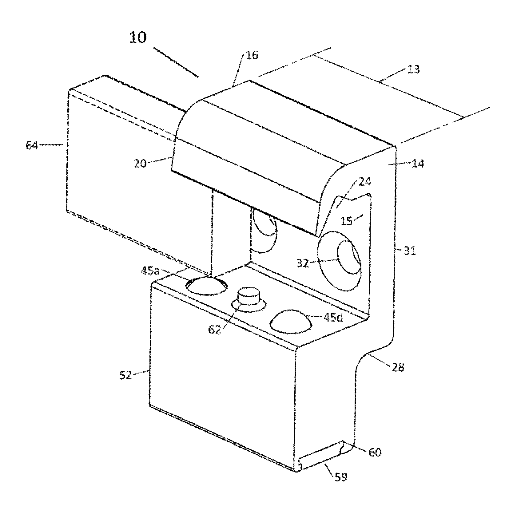
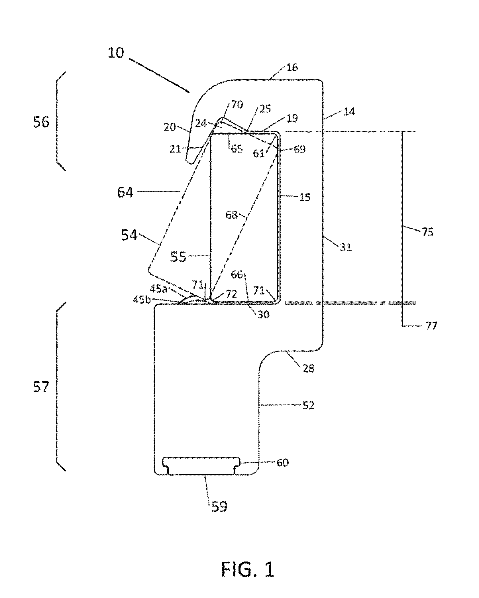
[0026]Now referring to the drawings, the modular rail adapter system is shown and generally illustrated in the figures. In accordance with the present invention the modular rail adapter 10 disclosed automates the task of latching an adapter to a DIN rail 64 without the need for users to manually latch adapter 10 to rail 64 and to remember to carry out this critical safety task. The aim is to allow users to simply snap adapter 10 to DIN rail 64 in one, continuous movement using a built-in, self-latching catch mechanism, as further described below.

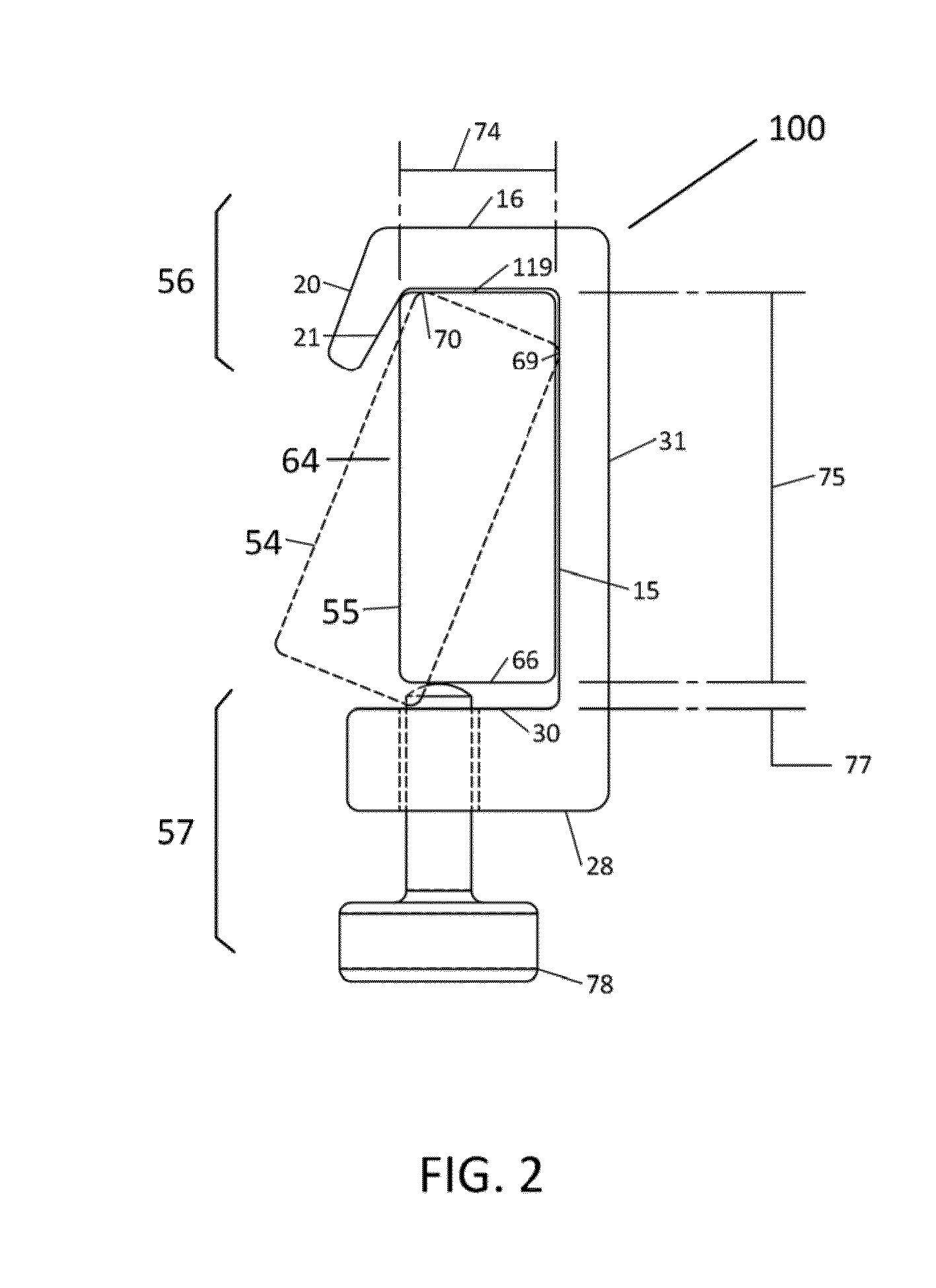
[0027]When a known DIN adapter 100 is in its vertical operating position 55, as shown in FIG. 2, it can only be removed from DIN rail 64 by inclining it against the rail until the lower return leg 28 clears the bottom edges of the rail at which point the adapter can be disengaged and removed from the rail. In known DIN adapter systems, this inclining motion requires a wide clearance gap 77 between the inner return leg surface 30 of an adapte...


PUM


Abstract

A modular rail adapter that automates latching an adapter to a DIN rail without the need for users to manually latch adapter to a rail. Users simply snap the adapter to the DIN rail in one, continuous movement using a built-in, self-latching catch mechanism. The present adapter eliminates, or greatly reduces the adapter clearance gap to enable a simple, safe, cost effective and user-friendly snap-on mechanism that doesn't require users to remember to latch the accessory being attached to a DIN rail.

Description

CROSS-REFERENCE TO RELATED APPLICATIONS[0001]This application is related to and claims priority from earlier filed U.S. Provisional Patent Application No. 61 / 754,160, filed Jan. 18, 2013.BACKGROUND OF THE INVENTION[0002]The present invention relates to a modular system for mounting components to a hospital rail system. More particularly, the present invention provides a modular mount that serves to interchangeably attach to the most common rail formats found in hospital facilities.[0003]Typical in a hospital, healthcare or medical environment, wall or equipment-mounted rails are provided which accept snap-on adapters for removably mounting various types of accessories. Such accessories are used daily in the medical environment, including O2 blenders, suction canisters, gas cylinders, shelves, storage baskets, scope hangers, diagnostic instruments, and other accessories. One of the technologies on which these rails and adapters are based was protected under now-expired patents issued...

Claims


Application Information

Patent Timeline
Patent Type & Authority Applications(United States)
IPC IPC(8): F16B17/00
CPCF16B17/00F16B7/22A61G12/008A61G12/005A61G13/101A61B90/57Y10T403/602F16B2200/10
Inventor BALLY, ALEXANDER
Owner BALLY ALEXANDER
Why Eureka
Try Eureka