Vegetation cutter

a cutter and vegetation technology, applied in the field of vegetation cutters, can solve the problems of clogging the intake aperture and affecting the airflow through the hollow tube of the frame rod, and achieve the effects of convenient storage, convenient carrying, and no deterioration of the aesthetics of the appearance of the vegetation cutter

Inactive Publication Date: 2014-07-31
MAKITA CORP
View PDF10 Cites 14 Cited by
  • Summary
  • Abstract
  • Description
  • Claims
  • Application Information

AI Technical Summary

Benefits of technology

[0010]Further, with the vegetation cutter where the frame rod is comprised of a front part rod and a rear part rod to be separably coupled together, the vegetation cutter will be convenient for carrying and for storing in a short space. Further, as the air intake aperture is located on the front part rod, the air taken in through the intake aperture will flow through the inside tube of the front part rod toward the motor in the cutter head, although the coupling ends of the front part rod and the rear part rod are provided with the connectors for supplying electric power from the power head

Problems solved by technology

However, if the motor housing is provided with an intake aperture for air, the water which may be attached on the grass may be taken in through the intake aperture inside the motor housing, and further the grass pieces cut by the rotary cutter may clog the

Method used


Image

  • Vegetation cutter
  • Vegetation cutter
  • Vegetation cutter

Examples


Embodiment Construction

[0023]The invention and its embodiments can now be better understood by turning to the following detailed description of the preferred embodiments with reference to the accompanying drawings. The embodiments of the vegetation cutter hereunder described are of an electric motor-driven type.

[0024]It should be expressly understood that the illustrated embodiments are presented just as practicable examples of the invention and that the invention as defined by the claims may be broader than the illustrated embodiments described below. In the drawing, like reference characters refer to like parts so that repetitive explanations may be omitted.

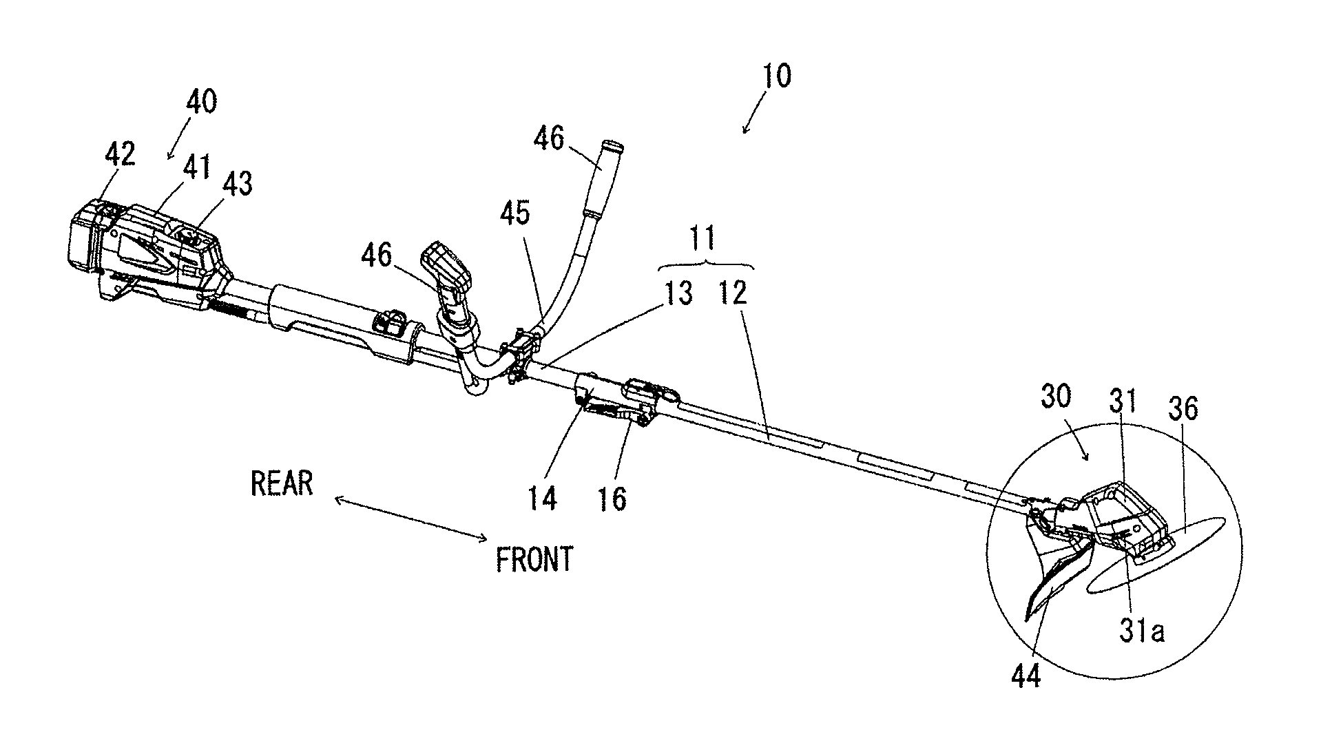
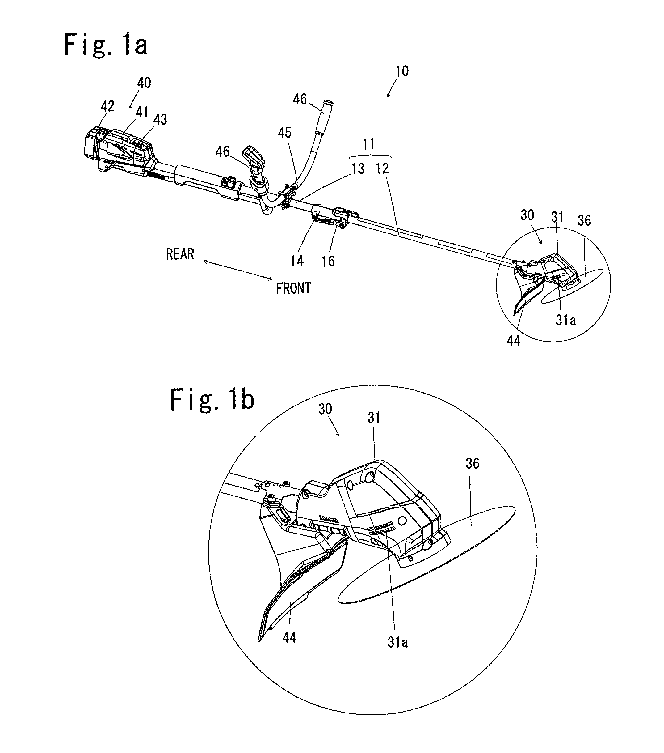
[0025]FIG. 1a illustrates an overall view of an embodiment of a vegetation cutter according to the present invention, in which the vegetation cutter 10 comprises a frame rod 11 of a hollow cylindrical tube extending longitudinally from front to rear, a cutter head 30 mounted on the front end portion of the frame rod 11, and a power head 40 mounted on...


PUM


Abstract

A vegetation cutter comprises a frame rod having a front end portion and a rear end portion, and assuming a hollow tube having an open front end; a cutter head mounted on the front end portion of the frame rod and including a drive motor, a cooling fan to be rotated by the drive motor, and a rotary cutter to be rotated by the drive motor; and a power head mounted on the rear end portion of the frame rod and providing electric power for the drive motor. The frame rod is provided with an air intake aperture located at a position rearward than the cutter head and communicating through the hollow tube toward the cutter head. The frame rod is comprised of a front part rod and a rear part rod separably coupled together by means of a tubular joint. The air intake aperture is located on the front part rod.

Description

FIELD OF THE INVENTION[0001]The present invention relates to a vegetation cutter such as a grass cutter, a lawn trimmer and a brush cutter, and more particularly to a vegetation cutter which comprises a frame rod and a cutter head mounted on the front end of the frame rod and including a motor housing which encloses a drive motor with a cooling fan and rotatably supports a rotary cutter below the motor housing, in which the frame rod is provided with an air intake aperture communicating through the frame rod to the motor housing.BACKGROUND OF THE INVENTION[0002]An example of a battery powered tool serving as a vegetation cutter is disclosed in U.S. Pat. No. 5,809,653, which comprises a frame rod (shaft, boom) in the shape of a hollow tube having an open front end, a cutter head (motor housing) mounted on the front end portion of the frame rod, and a power head (battery housing) mounted on the rear end of the frame rod. The cutter head of this vegetation cutter comprises a motor hous...

Claims


Application Information

Patent Timeline
IPC IPC(8): A01G3/053
CPCA01D34/90A01G3/053A01G3/088
Inventor MORITA, YOSHIFUMINOMURA, AKIHIRONOJIRI, HIROSHI
Owner MAKITA CORP
Why Eureka
Try Eureka