
Ladder

Active Publication Date: 2014-07-31
BASF AG
View PDF5 Cites 2 Cited by
  • Summary
  • Abstract
  • Description
  • Claims
  • Application Information

AI Technical Summary

Benefits of technology

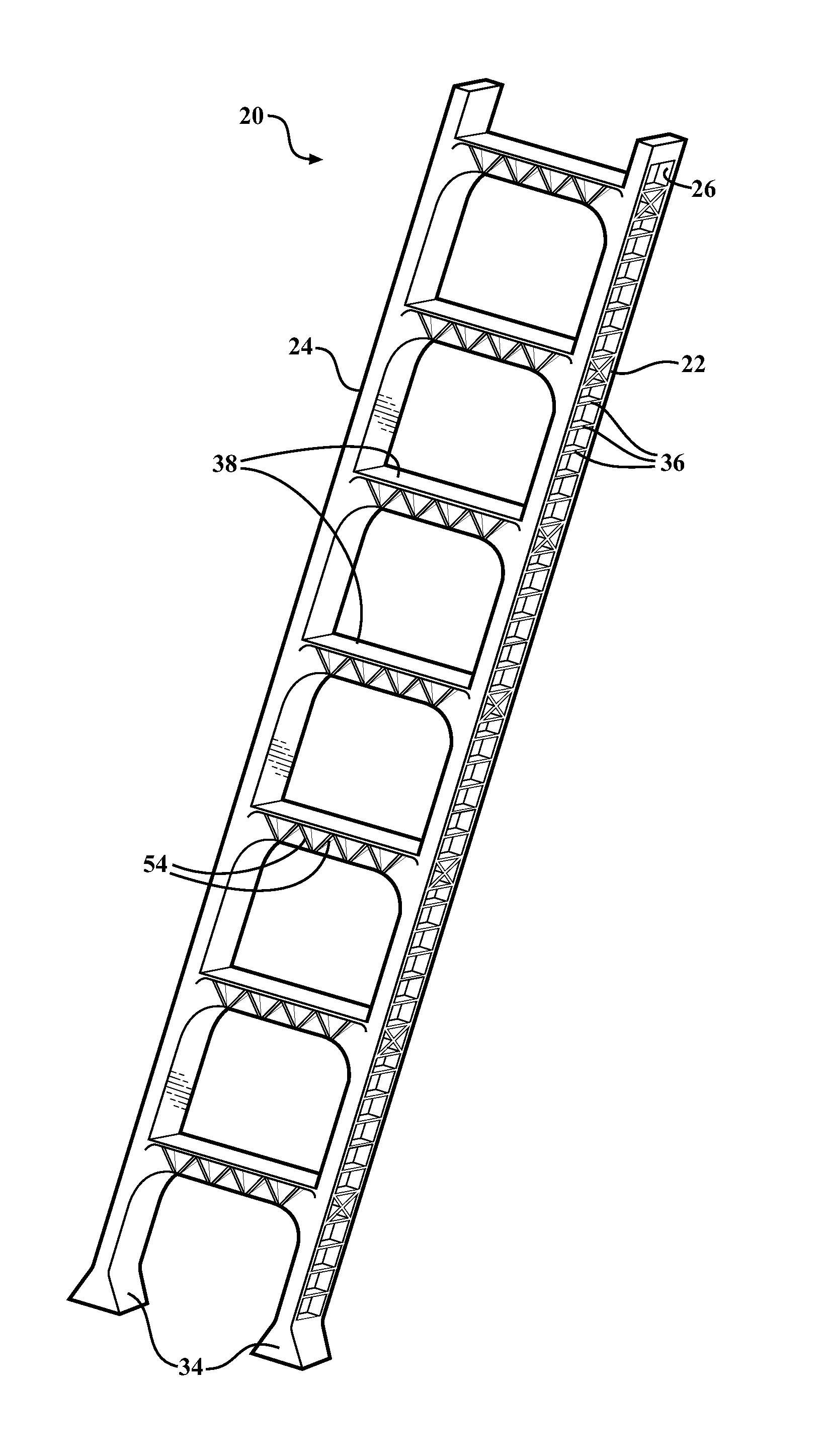
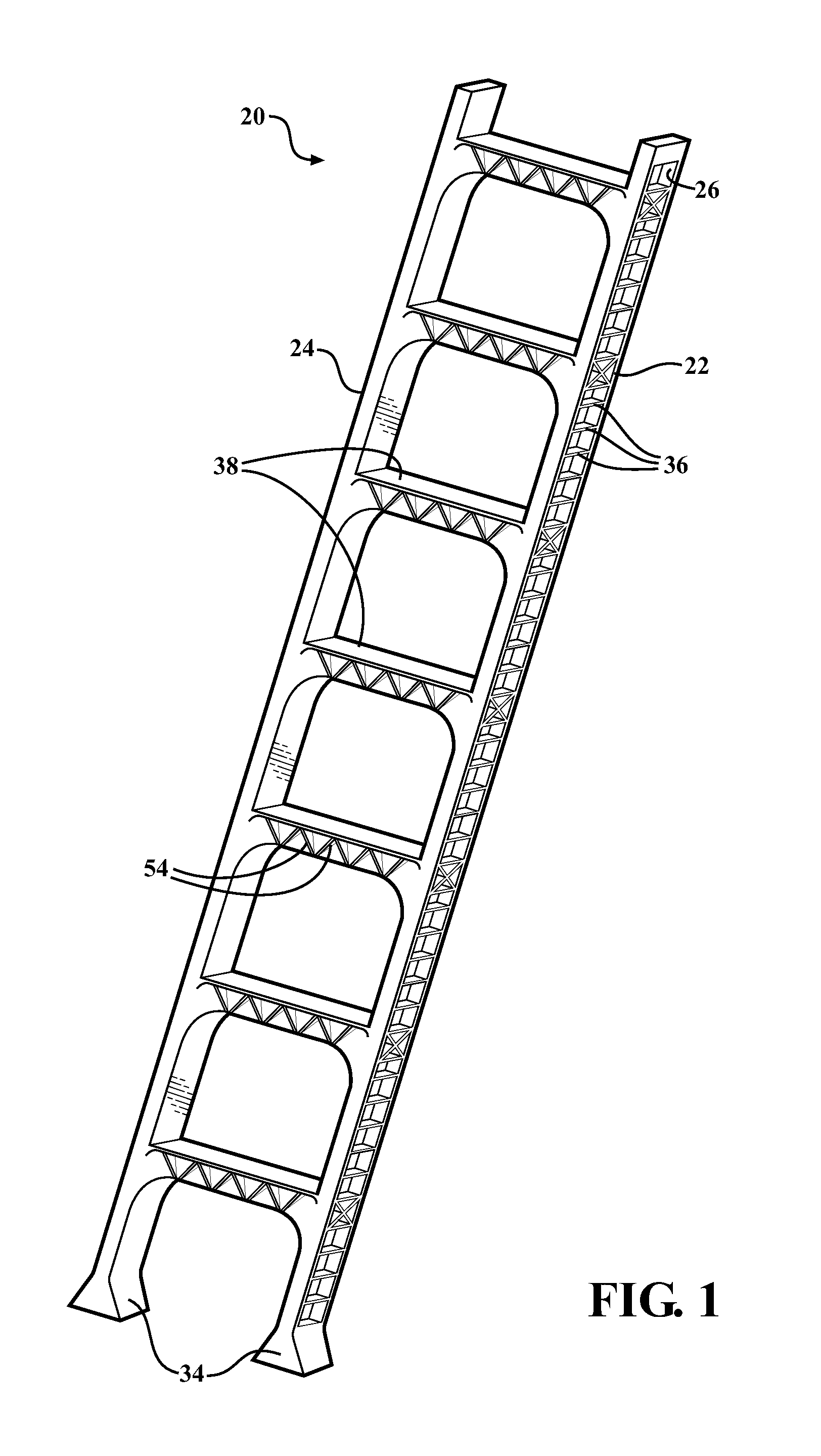
The invention makes a ladder stronger and stiffer by adding multiple rungs with horizontal and vertical parts and ribs between them. This design better spreads force and requires less material, making the ladder lighter and easier to use.

Problems solved by technology

However, even ladders formed from these materials may lack structural features which impart the ladder with sufficient strength and rigidity for use.
Ladders formed from metals or combinations of metals and fiberglass can also be heavy and therefore difficult to manipulate and use.
Additionally, ladders formed from metals generally require a significant amount of linkages, such as rivets or spot welding, therefore substantially increasing production time and cost of these ladders.
Use of metals in ladders is further prohibitive in view of the increased cost of metals, such as aluminum and steel.
While thermoplastics are often cheaper than metals, thermoplastics are not generally known for possessing those physical properties typical of metals, e.g. excellent strength and rigidity, which are required to form a safe, sturdy, and useful ladder.
Accordingly, ladders formed from thermoplastics generally require more material than ladders formed from metals to impart the thermoplastic ladders with sufficient strength and rigidity, resulting in thermoplastic ladders that are generally heavier and therefore more difficult to operate than ladders formed from metals.
Although thermoplastics reinforced with fiberglass have increased strength, ladders formed from these materials are still typically heavy and are therefore difficult to manipulate and operate.
Despite efforts using different materials such as metals, thermoplastics, or thermoplastics including reinforcing fibers to form ladders, concerns remain regarding the strength, rigidity, and weight of these ladders.

Method used


Image

  • Ladder
  • Ladder
  • Ladder

Examples


first embodiment

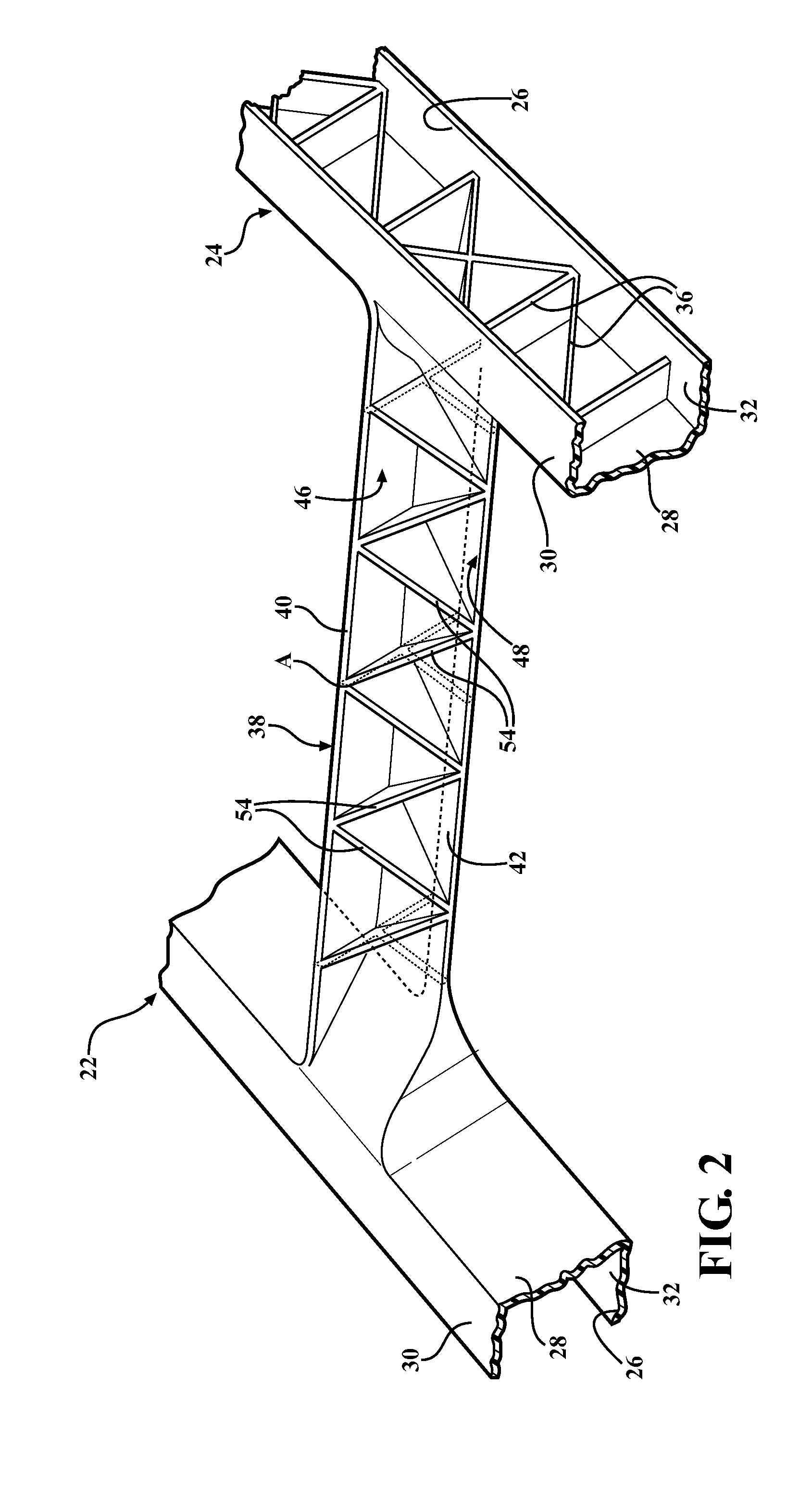
[0031]In another embodiment, the ribs 54 includes a first set of ribs and a second set of ribs spaced and opposite the first set of ribs as best shown in FIGS. 3-10. Typically, the first set of ribs extends from the bottom surface 46 of the horizontal portion 40 to the front surface 48 of the vertical portion 42 and the flange 52 if present. The second set of ribs typically extends from the bottom surface 46 of the horizontal portion 40 to the rear surface 50 of the vertical portion 42 and the flange 52 if present. In a first embodiment, the first set of ribs is generally perpendicular to the bottom surface 46 of the horizontal portion 40 and therefore to the front surface 48 of the vertical portion 42, and the flange 52, if present, as best shown in FIGS. 3 and 6. In this embodiment, the second set of ribs is generally perpendicular to the bottom surface 46 of the horizontal portion 40 and therefore to the rear surface 50 of the vertical portion 42, and the flange 52, if present.

second embodiment

[0032]In second embodiment, the first set of ribs includes at least one first pair of ribs intersecting at a first point of intersection A to define a substantially V-shape and the second set of ribs includes at least one second pair of ribs intersecting at a second point of intersection B to define a substantially inverted V-shape as best shown in FIGS. 5 and 8. In this embodiment, the second pair of ribs typically intersects at the second point of intersection B at any angle β, alternatively the angle β is from 10 to 120, alternatively from 30 to 90, and alternatively from 45 to 90, degrees. Typically, the angle β is equal to the angle α. However, it should be appreciated that the angle α and the angle β may be different. Typically, the second point of intersection B is aligned horizontally with and spaced vertically from the first point of intersection A of the first and second pair of ribs.

third embodiment

[0033]In third embodiment, the first set of ribs includes the at least one first pair of ribs intersecting at the first point of intersection A to define a substantially V-shape and ribs 54 that are perpendicular to the bottom surface 46 of the horizontal portion 40 and therefore to the front surface 48 of the vertical portion 42, and the flange 52, if present, as best shown in FIGS. 4 and 7. Additionally, the second set of ribs includes the at least one second pair of ribs intersecting at the second point of intersection B to define a substantially inverted V-shape and ribs 54 that are perpendicular to the bottom surface 46 of the horizontal portion 40 and therefore to the rear surface 50 of the vertical portion 42, and the flange 52, if present.

[0034]The ribs 54 provide the ladder 20, and more specifically the rungs 38, with excellent strength and rigidity. Accordingly, less material is required to imbue the ladder 20 with these physical properties than conventional ladders, contr...


PUM


Abstract

A ladder including a first stringer and a second stringer spaced transverse from each other is provided. Each of the first and second stringers defines a channel and includes a plurality of crosspieces disposed in the channels of the first and second stringers. A plurality of rungs are spaced along and coupled between the first and second stringers. Each of the rungs has a horizontal portion and a vertical portion extending from the first stringer to the second stringer. A plurality of ribs are spaced along and coupled between the horizontal and vertical portions of the rungs.

Description

BACKGROUND OF THE INVENTION[0001]1. Field of the Invention[0002]The subject invention generally relates to a ladder having excellent strength, rigidity, and weight.[0003]2. Description of the Related Art[0004]Generally, ladders, including fixed ladders, step ladders, step stools, and extension ladders, are formed from metals or combinations of metals and fiberglass. Metals and / or fiberglass are generally known to have excellent strength. However, even ladders formed from these materials may lack structural features which impart the ladder with sufficient strength and rigidity for use. Ladders formed from metals or combinations of metals and fiberglass can also be heavy and therefore difficult to manipulate and use. Additionally, ladders formed from metals generally require a significant amount of linkages, such as rivets or spot welding, therefore substantially increasing production time and cost of these ladders. Use of metals in ladders is further prohibitive in view of the increa...

Claims


Application Information

Patent Timeline
IPC IPC(8): E06C7/08
CPCE06C7/08E06C1/06E06C1/16E06C7/082
Inventor ZORNEY, PETER A.MCMASTER, WILLIAM J.BHOSALE, ANKUR
Owner BASF AG
Learn More