Light amount adjusting apparatus, lens barrel, and imaging apparatus

a technology of light amount and adjustment apparatus, which is applied in the direction of cameras, camera diaphragms, instruments, etc., can solve the problems of reducing the inability to ensure the space for the engaging part which engages with the driving source and extends from the blade driving ring, and the inability to ensure the quality of the image processing apparatus. , to achieve the effect of high speed reduction ratio

Active Publication Date: 2014-07-31
CANON KK
View PDF2 Cites 16 Cited by
  • Summary
  • Abstract
  • Description
  • Claims
  • Application Information

AI Technical Summary

Benefits of technology

[0010]The present invention provides, for example, a high-quality and high-accuracy light amount adjusting apparatus having a high speed reduction ratio.

Problems solved by technology

In this case, the shape of blur / the shape of surface reflection ghost generated from a point light source looks like a diamond, which leads to a reduction in quality and is not suitable for high-grade and highly accurate imaging apparatuses.
With this arrangement, a space for the engaging part which engages with the driving source and extends from the blade driving ring cannot be ensured.
Thus, the operating angle of the drive ring becomes small, resulting in a difficulty in ensuring desired resolution.
However, since the number of gear components is increased by one, the problems of backlash, rattling, or the like may occur, resulting in an adverse effect on the accuracy of the imaging apparatus.
However, since the rotation reference pins for the light amount adjusting blades are formed on the blade driving ring serving as a moving body, the shape of the opening may be deformed or a shift in the center axis of the opening may occur, resulting in an adverse effect on the quality of the imaging apparatus.

Method used


Image

  • Light amount adjusting apparatus, lens barrel, and imaging apparatus
  • Light amount adjusting apparatus, lens barrel, and imaging apparatus
  • Light amount adjusting apparatus, lens barrel, and imaging apparatus

Examples


Embodiment Construction

[0019]Hereinafter, preferred embodiments of the

[0020]present invention will now be described with reference to the accompanying drawings.

[0021]Firstly, a description will be given of the

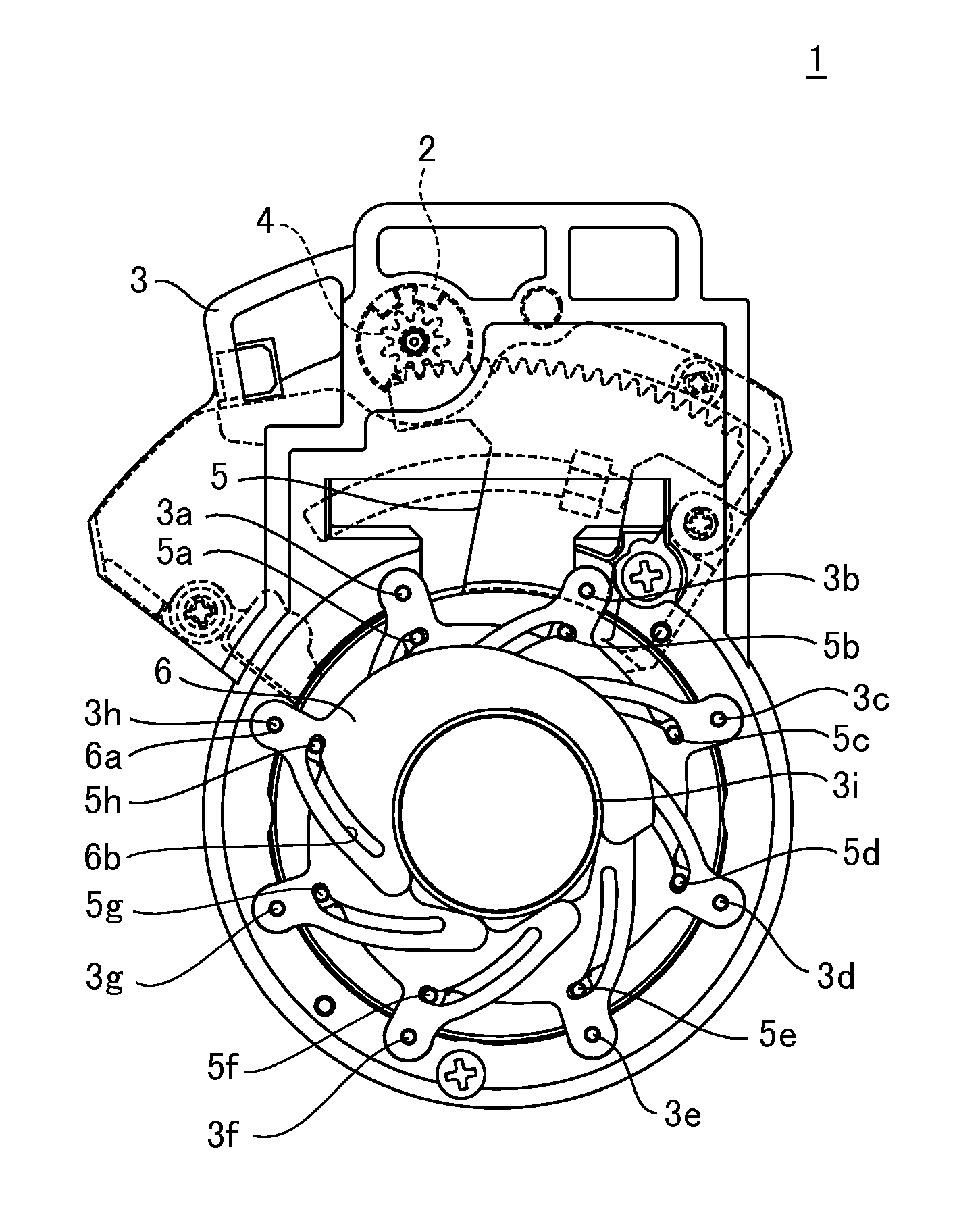
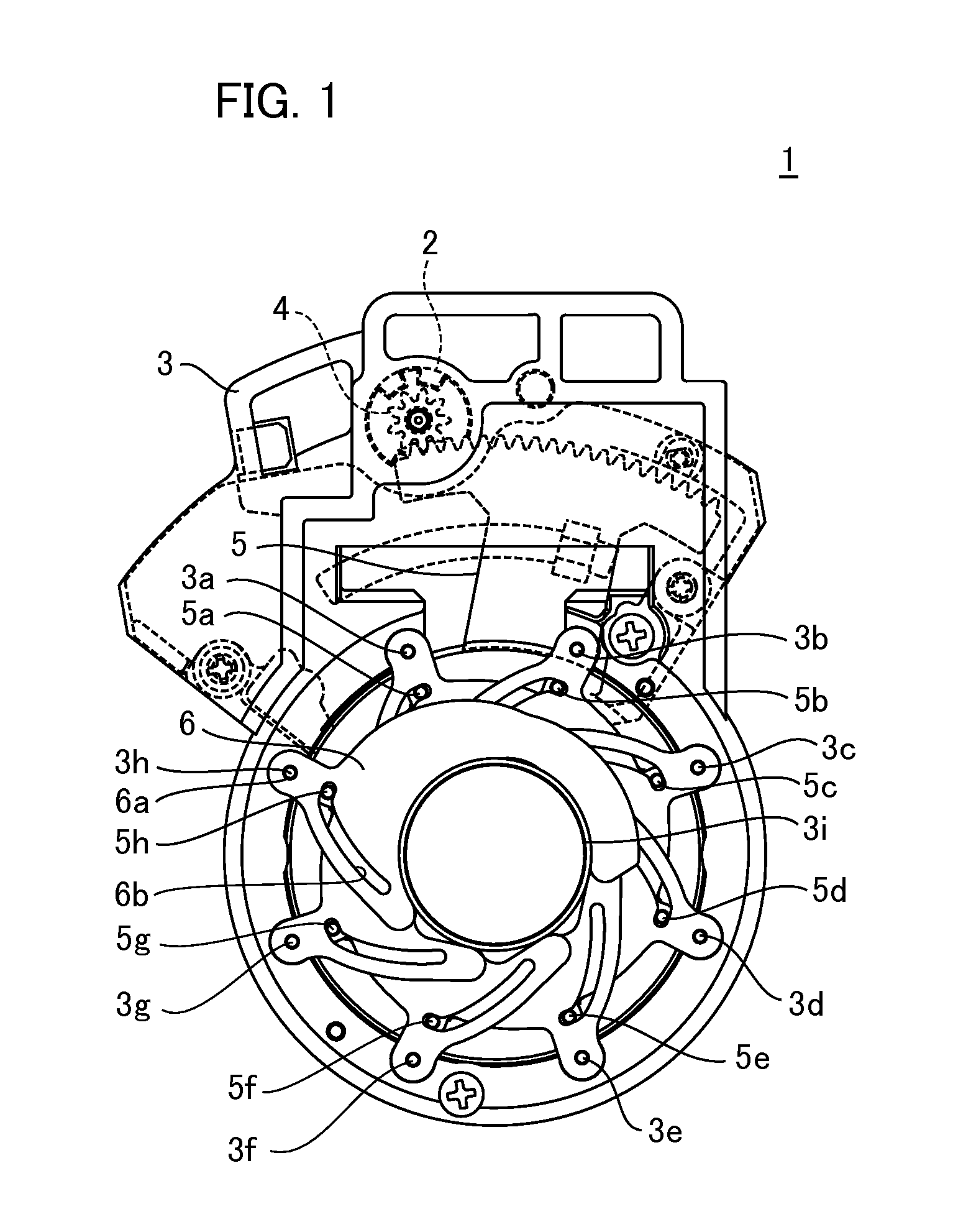
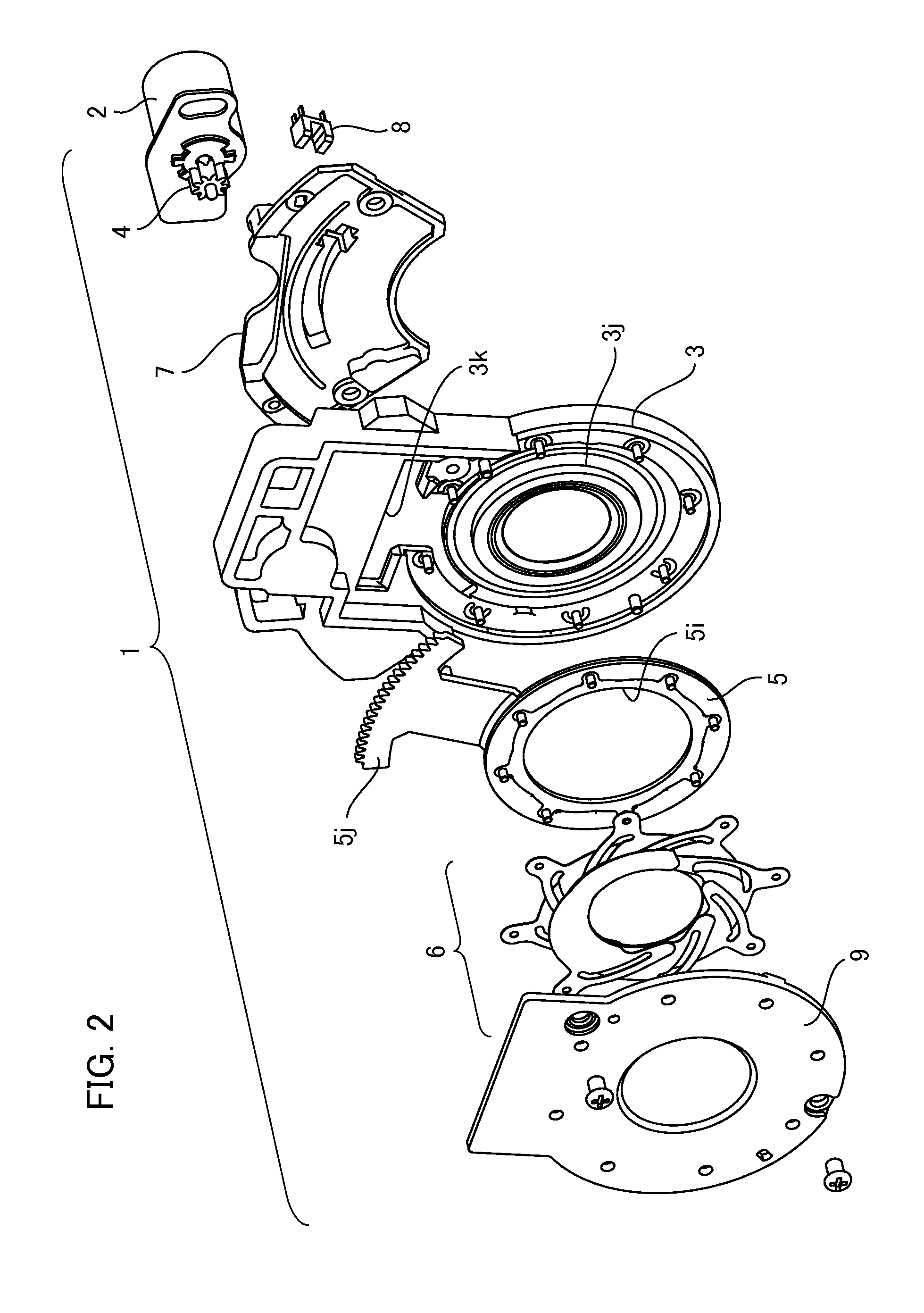
[0022]light amount adjusting apparatus of the present invention with reference to FIGS. 1 to 3. FIG. 1 is a diagram illustrating a configuration of a light amount adjusting apparatus according to one embodiment of the present invention. FIG. 2 is an exploded perspective view illustrating the light amount adjusting apparatus. FIG. 3 is a cross-sectional view illustrating the light amount adjusting apparatus. Firstly, a light amount adjusting apparatus 1 includes a base member 3, a driving source 2, a drive transmission member 4 (first contact part), a blade driving member 5, and a plurality of light amount adjusting blades 6.

[0023]The base member 3 has a base member opening 3i having an opening in a circular shape, a jointing unit 3j for pivotally join to the blade driving member 5, and a hole 3k for ...


PUM


Abstract

Provided is a light amount adjusting apparatus wherein a base member has a plurality of supporting parts for supporting the plurality of light amount adjusting blades and a second contact part is located outside a circle extending through the plurality of supporting parts, wherein a contact part between the second contact part and a first contact part is constituted at the other surface of the base member with respect to a surface having a jointing part between a blade driving member and the base member, and wherein, when the blade driving member is pivoted in the circumferential direction of an opening, a part of the blade driving member overlaps at least one of the supporting parts for supporting the light amount adjusting blades at a position offset in a direction parallel to the center axis of the opening.

Description

BACKGROUND OF THE INVENTION[0001]1. Field of the Invention[0002]The present invention relates to a light amount adjusting apparatus and an optical apparatus. More specifically, the present invention relates to a light amount adjusting device in optical apparatus in which a lens is exchangeable or optical apparatus formed integrally with a lens.[0003]2. Description of the Related Art[0004]Conventionally, light amount adjusting devices used for imaging apparatuses such as video cameras, digital cameras, and the like have a structure in which two light amount adjusting blades are movably sandwiched between a base plate provided with an opening on the optical axis thereof and a cover. The two light amount adjusting blades can linear-slidably move in relatively-opposite directions in a planer perpendicular to the optical axis and can flexibly change the shape of the opening so as to adjust light amount. In the conventional light amount adjusting apparatuses, the configuration number of l...

Claims


Application Information

Patent Timeline
Patent Type & Authority Applications(United States)
IPC IPC(8): G03B9/06
CPCG03B9/06
Inventor SATO, KATSUHIKO
Owner CANON KK
Why Eureka
Try Eureka