
Automated warehouse system

Active Publication Date: 2014-07-31
AMAZON TECH INC
View PDF6 Cites 28 Cited by
  • Summary
  • Abstract
  • Description
  • Claims
  • Application Information

AI Technical Summary

Benefits of technology

The patent describes an automated warehouse system that allows for efficient use of space by transferring loads into and from multiple storage areas. The system uses minimal floor space and can handle a large amount of traffic.

Problems solved by technology

An automated storage system that uses such a stacker crane requires a large amount of space.
However, when a load elevator-type of stacker crane is used as a transfer means in an automated warehouse system, it is necessary to provide movement rails for the stacker crane, which limits the ability to reduce space in a warehouse.
Moreover, when a plurality of stacker cranes is provided due to a high demand for transferring loads, it becomes necessary to provide other movement rails as well, making space reduction difficult.

Method used


Image

  • Automated warehouse system
  • Automated warehouse system
  • Automated warehouse system

Examples


first embodiment

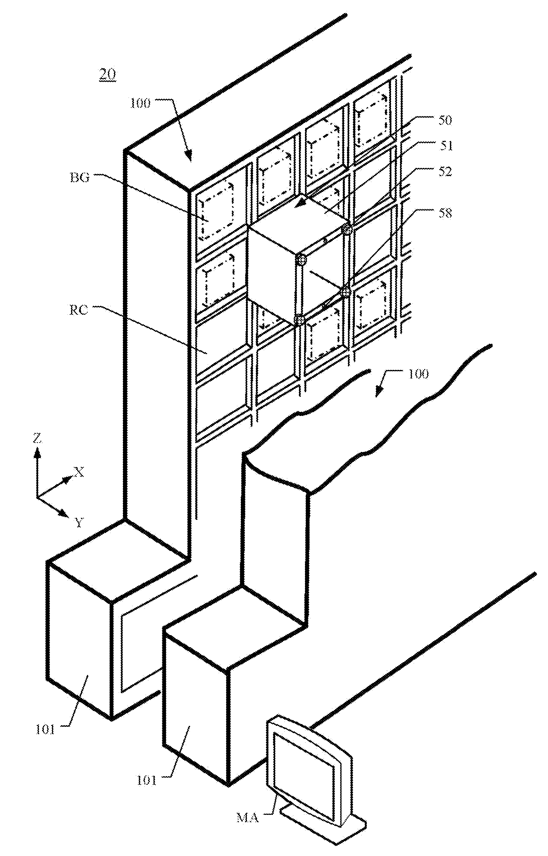
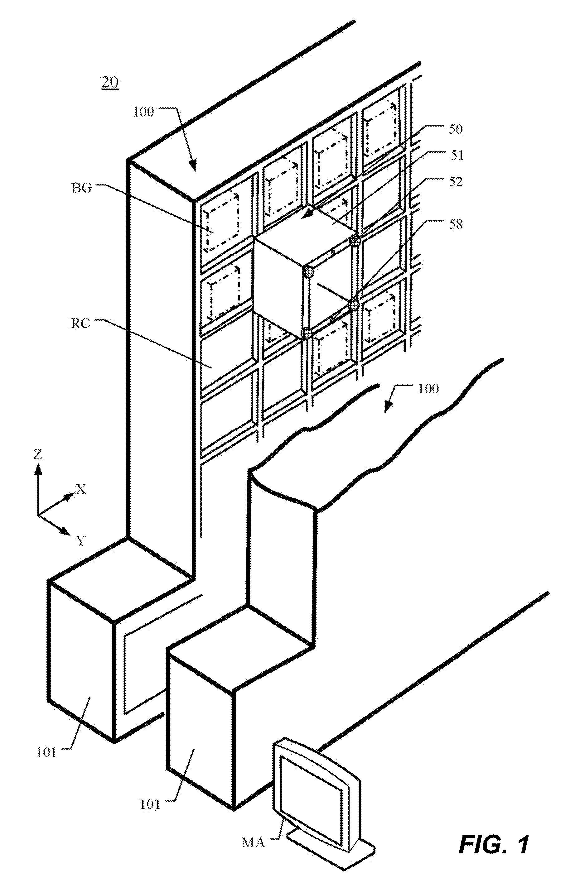
[0033]A first embodiment will be explained below based on the appended drawings. An overall perspective diagram of an automated warehouse system 20 according to the first embodiment is illustrated in FIG. 1. To facilitate viewing of the movable platform 50, the drawing omits a portion of one of the storage shelves 100.

[0034]Structure of the Automated Warehouse System 20

[0035]As illustrated in FIG. 1, the automated warehouse system 20 according to the first embodiment has a pair of storage shelves 100 having a plurality of storage areas RC. The storage shelves 100 have storage areas RC wherein loads BG are stored, and storage areas RC wherein loads BG are not yet stored. The movable platform 50 transfers a load BG from a loading / unloading port 101 (shown in FIG. 2 (A)) to a specific storage area RC, or transfers a load BG that is stored in a storage area RC to the loading / unloading port 101, following a movement instruction from a controlling portion MA.

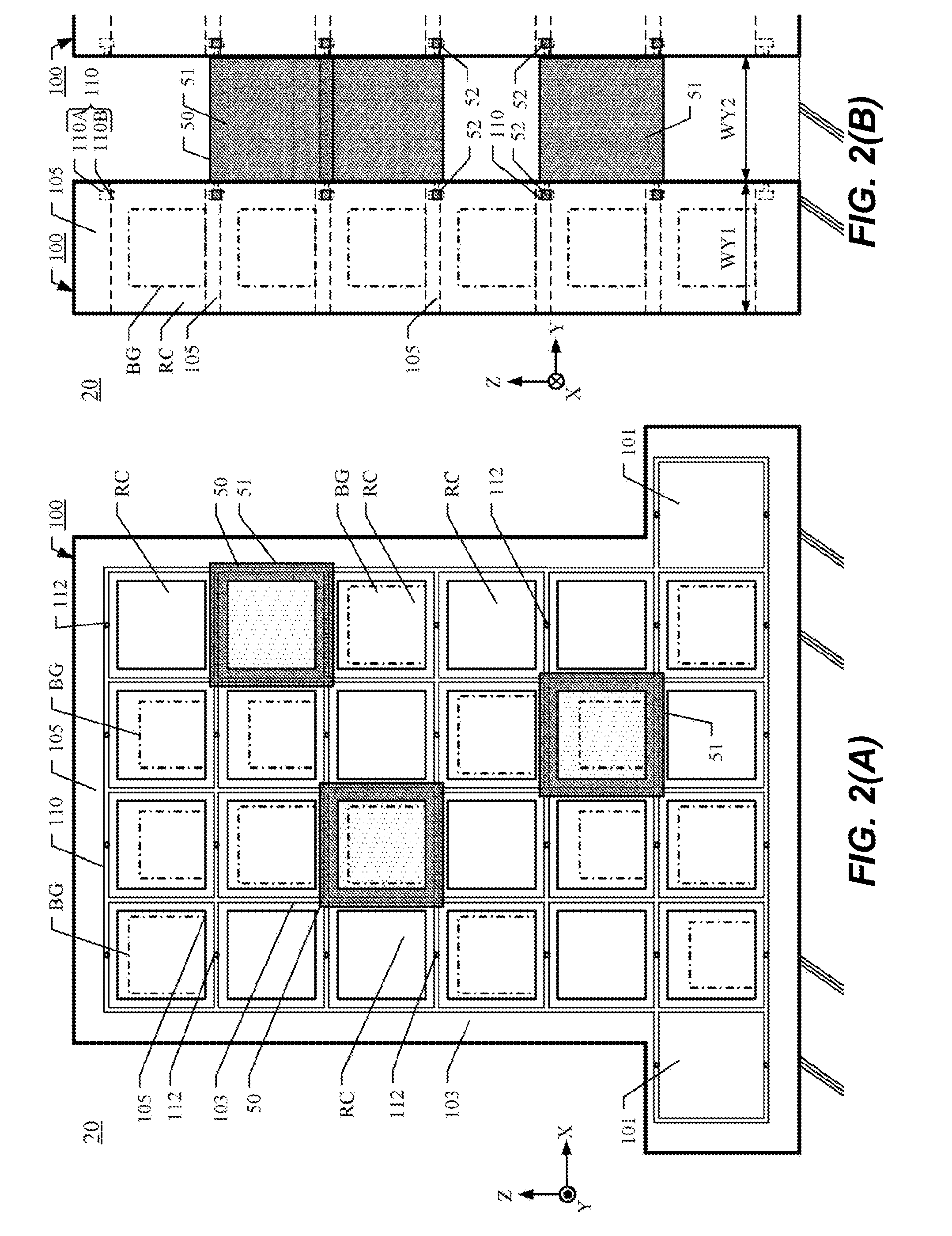
[0036]FIG. 2 (A) is a side vie...

second embodiment

[0085]An automated warehouse system 22 according to a second embodiment has a plurality of storage shelves 100 (100A through 100D). FIG. 9 is a side view diagram, viewed from the X direction, of the automated warehouse system 22.

[0086]The automated warehouse system 22 according to the second embodiment has four storage shelves 100 (100A through 100D), each having a plurality of storage areas RC. A plurality of movable platforms 50 is disposed between the storage shelves 100A and 100B. Similarly, a plurality of movable platforms 50 is disposed between the storage shelves 100B and 100C, and a plurality of movable platforms 50 is disposed between the storage shelves 100C and 100D. The Y-direction width WY1 of the storage shelves 100 and the Y-direction width WY2 of the movable platforms 50 are essentially identical.

[0087]The storage shelf 100B and the storage shelf 100C each have a plurality of movable platforms 50 disposed on both sides of each. Moreover, as illustrated in FIG. 4 or F...

third embodiment

[0089]An automated warehouse system 24 according to a third embodiment has a plurality of storage shelves 100 (100A through 100D). FIG. 10 is a side view diagram, viewed from the X direction, of the automated warehouse system 24.

[0090]The automated warehouse system 24 according to the third embodiment has four storage shelves 100 (100A through 100D), each having a plurality of storage areas RC. A plurality of movable platforms 50 is disposed between the storage shelves 100A and 100B. The storage shelf 100B and the storage shelf 100C adjoin each other, with no room for a movable platform 50 between the storage shelf 100B and the storage shelf 100C. A plurality of movable platforms 50 is disposed between the storage shelves 100C and 100D. The Y-direction width WY1 of the storage shelves 100 and the Y-direction width WY2 of the movable platforms 50 are essentially identical.

[0091]Even though the storage shelves 100B and storage shelf 100C adjoin each other, the movable platforms 50 on ...


PUM


Abstract

An automated warehouse system may require less space than conventional warehouse systems. The automated warehouse system is configured so that loads are stored in storage areas formed by vertically extending support pillars and horizontally extending beams. The loads are loaded into the storage areas, and the loads are unloaded from storage areas. The automated warehouse system comprises: vertical guide rails disposed on the support pillars; horizontal guide rails disposed on the beams; and a movable platform having a frame body and guide rollers, at least part of the frame body having the same rectangular shape as a shape of at least part of at least one of the storage areas and having vertical frame members and horizontal frame members, the guide rollers being disposed on the vertical frame members and engaging the vertical guide rails or disposed on the horizontal frame members and engaging the horizontal guide rails.

Description

BACKGROUND[0001]1. Technical Field[0002]The present disclosure generally relates to an automated warehouse system, and, in particular, relates to an automated warehouse system that transfers loads stored in storage areas.[0003]2. Description of the Related Art[0004]Conventional automated warehouse systems typically use a load elevator-type of stacker cranes as a transfer means. These stacker cranes are driven along travel guide rails, and are structured so as to move up and down along a guide frame portion that is disposed perpendicularly in relation to the travel guide rails. To enable these stacker cranes to move in relation to a plurality of storage areas that are arranged in a line, the travel guide rails are laid, from end to end, along the storage areas that are arranged in a line. An automated storage system that uses such a stacker crane requires a large amount of space. Moreover, often it is possible to provide only a single stacker crane for a single travel guide rail. In ...

Claims


Application Information

Patent Timeline
IPC IPC(8): B65G1/04
CPCB65G1/0492B65G1/0407B65G1/0435
Inventor KAWANO, YASUSHI
Owner AMAZON TECH INC
Learn More