Drive Train Of A Vehicle

a technology of a drive train and a drive shaft, which is applied in the direction of positive displacement liquid engines, hybrid vehicles, piston pumps, etc., can solve the problems of corresponding drag losses in addition to the output of additional torque, and achieve the effects of low construction effort or expense, increased torque that can be introduced into the drive train, and low construction cos

Inactive Publication Date: 2014-07-31
LINDE HYDRAULICS
View PDF8 Cites 11 Cited by
  • Summary
  • Abstract
  • Description
  • Claims
  • Application Information

AI Technical Summary

Benefits of technology

[0014]To accomplish this object, the invention teaches that the charge pump can be operated as a pump and as a motor. When operated as a pump, the charge pump takes in hydraulic fluid from a tank on the suction side and delivers it into a charge pressure line which leads to a charging circuit. When the charge pump is operated as a motor, hydraulic fluid can be supplied to the suction side from the hydraulic accumulator. In the drive train of the invention, therefore, the hydraulic pump of the working hydraulics and the charge pump can each be operated as a motor with hydraulic fluid from the hydraulic accumulator. Because of the motor operation of the charge pump of the invention, the torque that can be introduced into the drive train can be increased with little additional construction effort or expense. No complex or expensive modifications to the hydraulic pump of the working hydraulics are thereby necessary so that, when the hydraulic pump and the charge pump are operated as motors, a high total torque can be introduced into the drive train with little added construction effort or expense. In addition, because the hydraulic pump (which is already present in the drive train for the working hydraulics) and the charge pump (which is already present in the drive train) are used to introduce a torque, this provides advantages with regard to the efficiency and the space occupied by the drive train. No additional hydraulic motors are required in the drive train that are operated with hydraulic fluid from the hydraulic accumulator and which are used only to deliver additional torque to the drive train and which cause corresponding drag losses in addition to the output of an additional torque.
[0015]In one advantageous embodiment of the invention, the hydraulic pump is in the form of a hydraulic starter to start the internal combustion engine which has a start-stop function. When the hydraulic pump is operated as a motor, in which the hydraulic pump is driven with hydraulic fluid from the hydraulic accumulator, a hydraulic starter to start the internal combustion engine can be formed in a simple manner to achieve a start-stop function.
[0016]In one advantageous embodiment of the invention, the charge pump functions as a hydraulic starter to start the internal combustion engine with a start-stop function and / or functions as a booster drive to assist the internal combustion engine which is already running. When the charge pump of the invention is operated as a motor, the torque for the starting process can be easily increased, for example during a cold start, to achieve a torque that is sufficient to start the shut-off internal combustion engine or, with a corresponding limitation of the pressure on the suction side of the hydraulic pump and motor operation, to generate a torque that is sufficient to start the shut-off internal combustion engine. With a charge pump that can be operated as a motor in this manner, a booster drive can be achieved and an additional torque can be introduced into the drive train, with which the running internal combustion engine can be assisted during an acceleration process or during traction operation of the vehicle at a steady speed, at a target speed and during the actuation of the working hydraulics. The hydrostatic booster drive provided by the charge pump makes it possible to reduce the amount of fuel used by the internal combustion engine and to downsize the internal combustion engine.

Problems solved by technology

No additional hydraulic motors are required in the drive train that are operated with hydraulic fluid from the hydraulic accumulator and which are used only to deliver additional torque to the drive train and which cause corresponding drag losses in addition to the output of an additional torque.

Method used


Image

  • Drive Train Of A Vehicle
  • Drive Train Of A Vehicle
  • Drive Train Of A Vehicle

Examples


Embodiment Construction

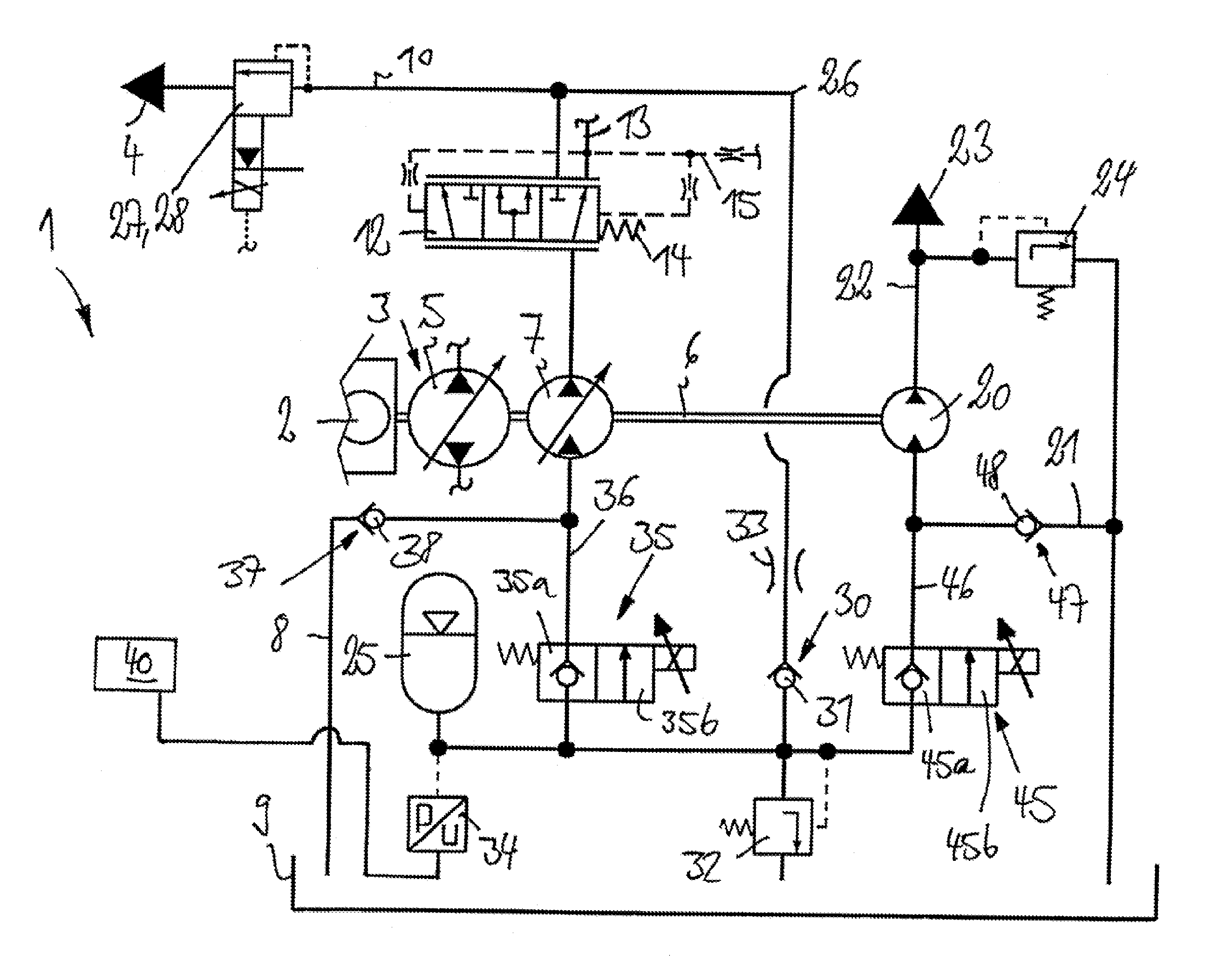
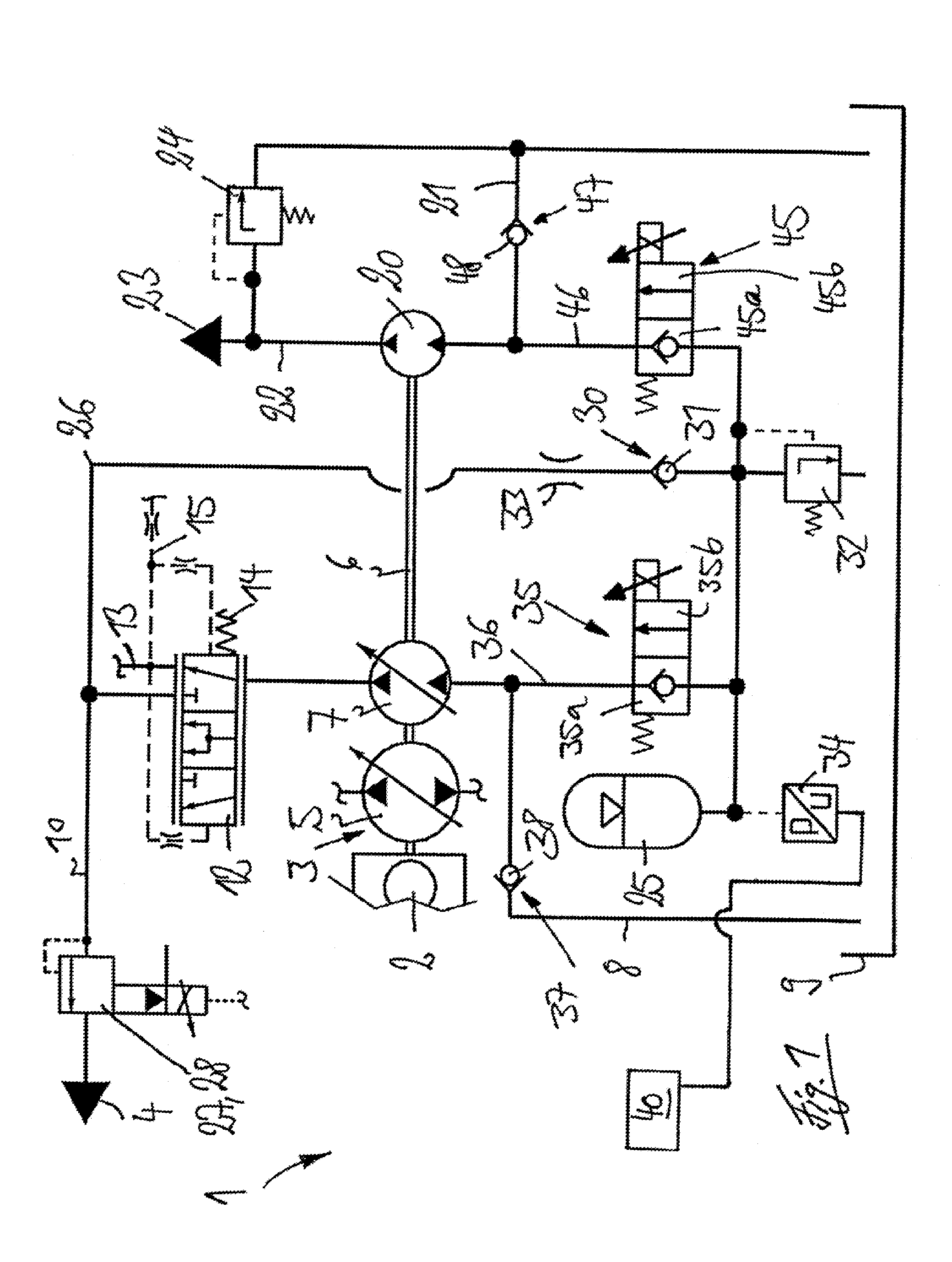
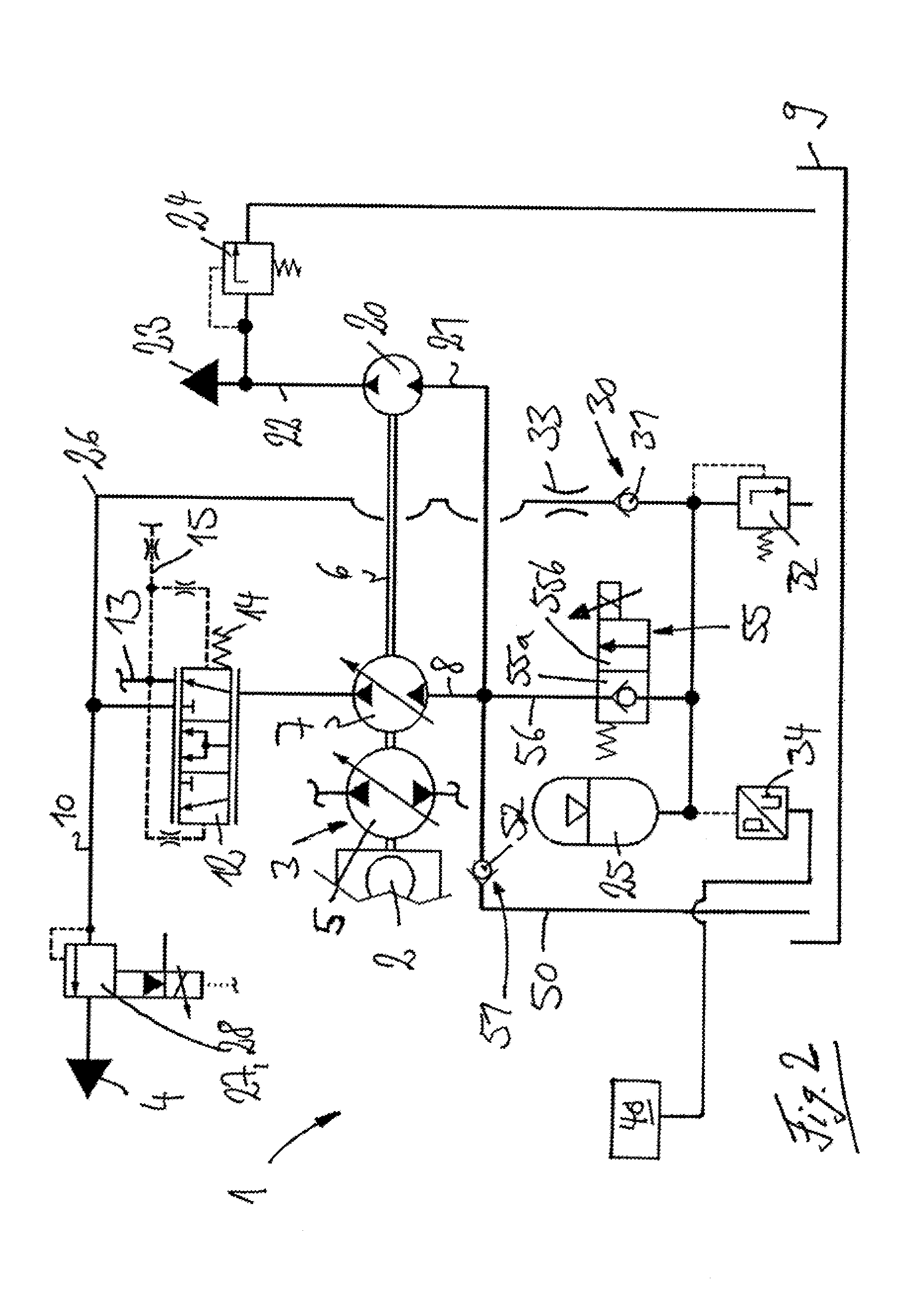
[0042]FIG. 1 is a schematic illustration of a drive train 1 of the invention of a mobile machine, e.g., of an industrial truck or a piece of construction or agricultural equipment.

[0043]The drive train 1 includes an internal combustion engine 2, such as a diesel engine, a traction drive 3 driven by the internal combustion engine 2, and working hydraulics 4 driven by the internal combustion engine 2.

[0044]In the illustrated exemplary embodiment, the traction drive 3 is a hydrostatic traction drive which includes a variable displacement drive pump 5 driven by a connection with an output shaft 6 of the internal combustion engine 2. The traction pump 5 is in communication with one or more fixed or variable intake hydraulic motors in a closed-circuit, which intake hydraulic motors are in an operative connection with the driven wheels of the machine in a conventional manner.

[0045]The traction drive 3 can alternatively be an electric traction drive with an electric generator driven by the ...


PUM


Abstract

A drive train (1) includes an internal combustion engine (2) and working hydraulics (4) having at least one hydraulic pump (7). When operated as a pump, the hydraulic pump (7) sucks hydraulic fluid from a tank (9) and delivers into a delivery line (10) that leads to the working hydraulics (4). When operated as a motor, the hydraulic pump (7) is supplied with hydraulic fluid from a hydraulic accumulator (25). The drive train (1) has a charge pump (20) to supply a charging circuit (23). The charge pump (20), when operated as a pump, sucks hydraulic fluid out of the tank (9) and delivers into a charge pressure line (22) that leads to a charging circuit (23), and the charge pump (20) when operated as a motor is supplied with hydraulic fluid from the hydraulic accumulator (25).

Description

CROSS REFERENCE TO RELATED APPLICATION[0001]This application claims priority to German Application No. DE 102012111296.7 filed Nov. 22, 2012, which is herein incorporated by reference in its entirety.BACKGROUND OF THE INVENTION[0002]1. Field of the Invention[0003]This invention relates to a drive train of a vehicle, such as a mobile machine, with an internal combustion engine and working hydraulics driven by the internal combustion engine. The working hydraulics have at least one hydraulic pump driven by the internal combustion engine, which hydraulic pump can be operated as a pump and as a motor. When operated as a pump, the hydraulic pump takes in hydraulic fluid from a tank on a suction side and delivers into a delivery line that leads to the working hydraulics. When operated as a motor, the hydraulic pump can be supplied with hydraulic fluid from a hydraulic accumulator on the suction side. The drive train has a charge pump driven by the internal combustion engine to supply a ch...

Claims


Application Information

Patent Timeline
Patent Type & Authority Applications(United States)
IPC IPC(8): F04B35/00
CPCF04B35/002F15B2211/20523F15B2211/851E02F9/2217F02N7/00B66F9/22F15B2211/20546F15B1/033E02F9/2289F02N11/0814F15B2211/20576F15B2211/212E02F9/2296F15B1/024F15B2211/88F15B2211/613F02N7/08E02F9/2292F15B2211/781F15B2211/20569B60K2006/126B60K6/12Y02T10/62B60W20/19
Inventor KRITTIAN, LUKASSTEIGERWALD, MARTINOBERHAUSSER, MARTINLANGEN, ALFRED
Owner LINDE HYDRAULICS
Why Eureka
Try Eureka