Crimp terminal

a crimp terminal and open-barrel technology, applied in the direction of electrical equipment, connections, effected by permanent deformation, etc., can solve the problems of deterioration of crimping performance, and achieve the effect of reducing the deformation of the terminal, increasing the stress that acts on the conductor (an element wire) of the electrical wire, and increasing the cross-sectional secondary momen

Active Publication Date: 2014-07-31
YAZAKI CORP
View PDF23 Cites 11 Cited by
  • Summary
  • Abstract
  • Description
  • Claims
  • Application Information

AI Technical Summary

Benefits of technology

[0013]The present invention aims at providing a crimp terminal that can suppress change of a serration angle (an angle between an extension surface of an inner bottom surface and an inner side surface of a concave serration) in a state after crimping in order to improve crimping performance by increasing a stress applied to a conductor of an electrical wire, and making longer a relative sliding distance between the terminal and the conductor.
[0016]According to the crimp terminal of the first aspect of the present invention, a number of circular concave portions are provided in the inner surface of the conductor crimping portion as the concave serrations so as to be scattered in a state of being spaced aside from one another. The diameter of each circular concave portion is set within the range of 0.15 (the error range is ±0.04) mm to 0.8 (the error range is ±0.04) mm. The serration angle between the extension surface of the inner bottom surface and the inner side surface of each circular concave portion is set within the range of 60 to 90 degrees. The shortest distance of the flat surface portion between the peripheries of the mutually adjacent circular concave portions is set to be 0.17 (the error range is ±0.09) mm. Therefore, a cross-sectional secondary moment of a portion in which the serrations are formed can be remarkably increased as compared with a case where serrations include rectangular concave portions or a case where they include grooves having rectangular cross sections. Accordingly, the cross-sectional secondary moment becomes higher, whereby tilt deformation of the inner side surfaces of the circular concave portions at the time of crimping, i.e., decrease of the serration angle (angle between the extension surface of the inner bottom surface and the inner side surface of each circular concave portion) in the state after crimping can be suppressed to be small, and catch of the peripheries and the inner side surfaces of the circular concave portions with the conductor in which plastic deformation is caused can be strengthened. As a result of it, the stress that acts on the conductor (an element wire) of the electrical wire can be increased as much as deformation of the terminal becomes smaller, and the relative sliding distance between the terminal and the conductor can be made longer to increase the adhesion amount of the terminal and the conductor, and thus the crimping performance (electrical and mechanical coupling performance) can be improved.
[0017]According to the crimp terminal of the second aspect of the present invention, the diameter of each circular concave portion is set to be 0.3 (the error range is ±0.04) mm. The serration angle between the extension surface of the inner bottom surface and the inner side surface of each circular concave portion is set to be 70 degrees. The shortest distance of the flat surface portion between the peripheries of the mutually adjacent circular concave portions is set to be 0.15 mm. Therefore, a cross-sectional secondary moment of serration portions can be effectively increased, and deformation of the serration angle in the state after crimping can be suppressed to be as small as possible. As a result of it, the stress that acts on the conductor (element wire) of the electrical wire can be increased, and the relative sliding distance between the terminal and the conductor can be made longer, and thus the crimping performance can be much more improved.

Problems solved by technology

As a result of it, there is a problem of leading to deterioration of the crimping performance.

Method used


Image

  • Crimp terminal
  • Crimp terminal
  • Crimp terminal

Examples


first embodiment

[0037]FIG. 3 is an external perspective view of a crimp terminal. FIG. 4 is a plan view showing an expanded shape of a conductor crimping portion of the crimp terminal. FIG. 5 is an enlarged cross-sectional view of small circular concave portions in a state before crimping of the conductor crimping portion. FIGS. 6(a) to 6(d) are enlarged cross-sectional views schematically and sequentially showing a condition in which a conductor gets into the small circular concave portion of the conductor crimping portion while causing a plastic deformation at the time of crimping.

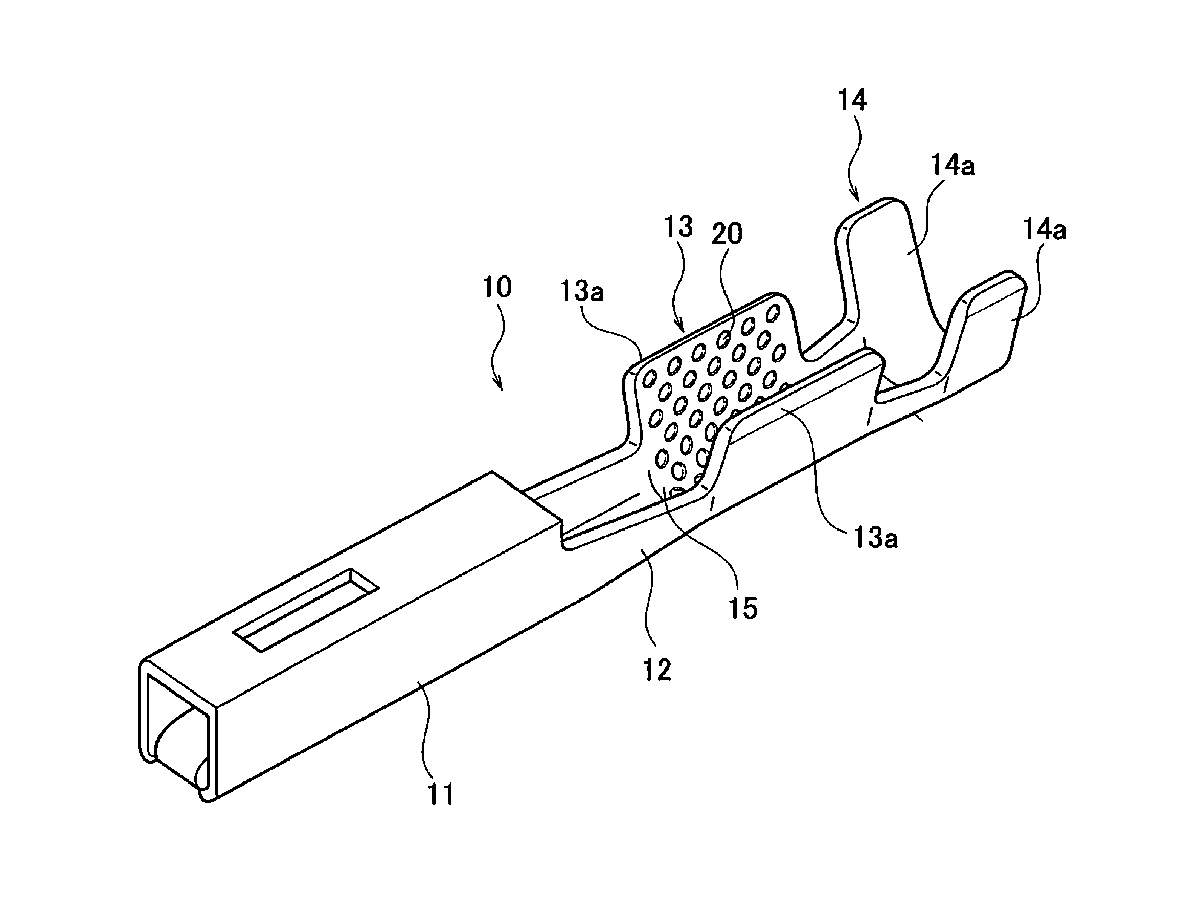
[0038]As shown in FIG. 1, a crimp terminal 10 is a female terminal and includes an electrical connection portion 11, a link portion 12, a conductor crimping portion 13 and a sheath crimping portion 14. The box-type electrical connection portion 11 is provided at a front in a longitudinal direction of the terminal (in a longitudinal direction of a conductor of an electrical wire connected to the terminal, i.e., in a dire...

second embodiment

[0063]FIG. 8 is a cross-sectional view of the small circular concave portions 20 as the serration in a crimp terminal according to a second embodiment of the present invention.

[0064]In the crimp terminal of the present embodiment, the serration angle θ between the extension surface 21a of the inner bottom surface 21 and the inner side surface 22 of each small circular concave portion 20 is set to be 70 degrees.

[0065]The diameter “d” of the inner bottom surface of the small circular concave portion 20 is set to be 0.3 mm. The shortest distance “b” of a flat surface portion between peripheries of mutually adjacent small circular concave portions 20 is set to be 0.15 mm.

[0066]In this case, r1 and r2 of the model used for calculating a cross-sectional secondary moment have values of 0.15 mm and 0.3 mm, respectively. It is to be noted that a radius of a top surface of the concave portion 20 is not employed because a round is applied to the periphery thereof and the radius is difficult to...

third embodiment

[0068]FIG. 11 is explanatory views of a crimp terminal according to a third embodiment of the present invention. Specifically, FIG. 11(a) is a plan view showing an expanded shape of a conductor crimping portion, and FIG. 11(b) is an arrow cross-sectional view taken along a line A-A of FIG. 11(a).

[0069]In the present embodiment, in order to reduce a size of the terminal, the number of small circular concave portions 20 provided as the serrations is less than that in the first embodiment.

[0070]In addition, linear convex portions 25 for restricting extension in a front-rear direction of the conductor of the electrical wire at the time of crimping are provided at a front and a rear of a region where the small circular concave portions 20 as the serrations are scattered, so as to intersect in a terminal width direction. The other configurations are similar to that of the first embodiment. Accordingly, the small circular concave portions 20 are provided similarly to the first embodiment, ...


PUM


Abstract

Concave serrations are provided in an inner surface of a conductor crimping portion of a crimp terminal. A number of circular concave portions are provided in the inner surface of the conductor crimping portion as the concave serrations so as to be scattered in a state of being spaced aside from one another. A diameter of an inner bottom surface of each circular concave portion is set within a range of 0.15 (an error range is ±0.04) mm to 0.8 (the error range is ±0.04) mm. A serration angle between an extension surface of the inner bottom surface and an inner side surface of each circular concave portion is set within a range of 60 to 90 degrees. A shortest distance of a flat surface portion between peripheries of mutually adjacent circular concave portions is set to be 0.17 (the error range is ±0.09) mm.

Description

CROSS REFERENCE TO RELATED APPLICATION[0001]This is a continuation application based on PCT application No. PCT / JP2012 / 075124 filed on Sep. 28, 2012, which claims the benefit of priority from Japanese Patent Application No. 2011-220776 filed on Oct. 5, 2011, the entire contents of which are incorporated by reference herein.BACKGROUND OF THE INVENTION[0002]1. Field of the Invention[0003]The present invention relates to an open-barrel type crimp terminal having concave serrations in an inner surface of a conductor crimping portion having a U-letter shaped cross section.[0004]2. Description of the Related Art[0005]Conventionally, a general crimp terminal is, for example, provided with an electrical connection portion, a conductor crimping portion, and a sheath crimping portion as shown in Patent Literature 1 (Japanese Patent Application Laid-Open Publication No. 2010-198776). The electrical connection portion is provided at a front in a longitudinal direction of the terminal (in a same...

Claims


Application Information

Patent Timeline
Patent Type & Authority Applications(United States)
IPC IPC(8): H01R4/18
CPCH01R4/188
Inventor ITO, YOSHITAKAKONDOU, TAKAYAONUMA, MASANORI
Owner YAZAKI CORP
Why Eureka
Try Eureka