Check patentability & draft patents in minutes with Patsnap Eureka AI!

Power conditioner system and power-storage power conditioner

Active Publication Date: 2014-08-07
KYOCERA CORP +1
View PDF14 Cites 28 Cited by
  • Summary
  • Abstract
  • Description
  • Claims
  • Application Information

AI Technical Summary

Benefits of technology

The patent text describes a power conditioner system and a power-storage power conditioner that can supply power to a major load without needing to change the connection of the load in case of a power failure. This system compensates for any shortage of power by using the output power of an independent-power-storage unit. Overall, the technical effect of this patent is to provide a more efficient and reliable solution for ensuring power supply in the event of a power failure.

Problems solved by technology

In this case, however, it is assumed that simple installment of the power-generation power conditioner and the power-storage power conditioner separately from each other may cause the following disadvantages.
For example, when the power-generation power conditioner is focused on, in case of the grid power failure, an major load needs to be made offline from a system outlet connected to the grid and connected to an independent outlet connected to an independent output terminal of the power-generation power conditioner, that is, the major load requires a connection change, which is troublesome.
Moreover, when solar panels are in use as the power generation equipment, since an output thereof depends on an amount of solar radiation, the major load may not be stably powered regardless of change of its connection to the independent outlet.
Especially, when the grid power failure occurs during nighttime, power generated during daytime is unavailable and thus the major load may not be powered.
Also, even when the grid power failure is not occurred, at the time of output suppression due to an increase in a system voltage, date / time designated by a calendar function, or an offline instruction by a PCS (Power Conditioner Subsystem) communication, the generated power is bound to be discarded, wasting generated power energy.
However, in case of the grid power failure, in the same manner as the power-generation power conditioner, the trouble of changing connection of the major load from the grid outlet to the independent outlet of the power-storage power conditioner is required.
In case of the grid power failure, further, since the power generation equipment is made offline from the grid, the power generated by the power generation equipment may not be stored in the power storage equipment, wasting the generated power energy.

Method used


Image

  • Power conditioner system and power-storage power conditioner
  • Power conditioner system and power-storage power conditioner
  • Power conditioner system and power-storage power conditioner

Examples


first embodiment

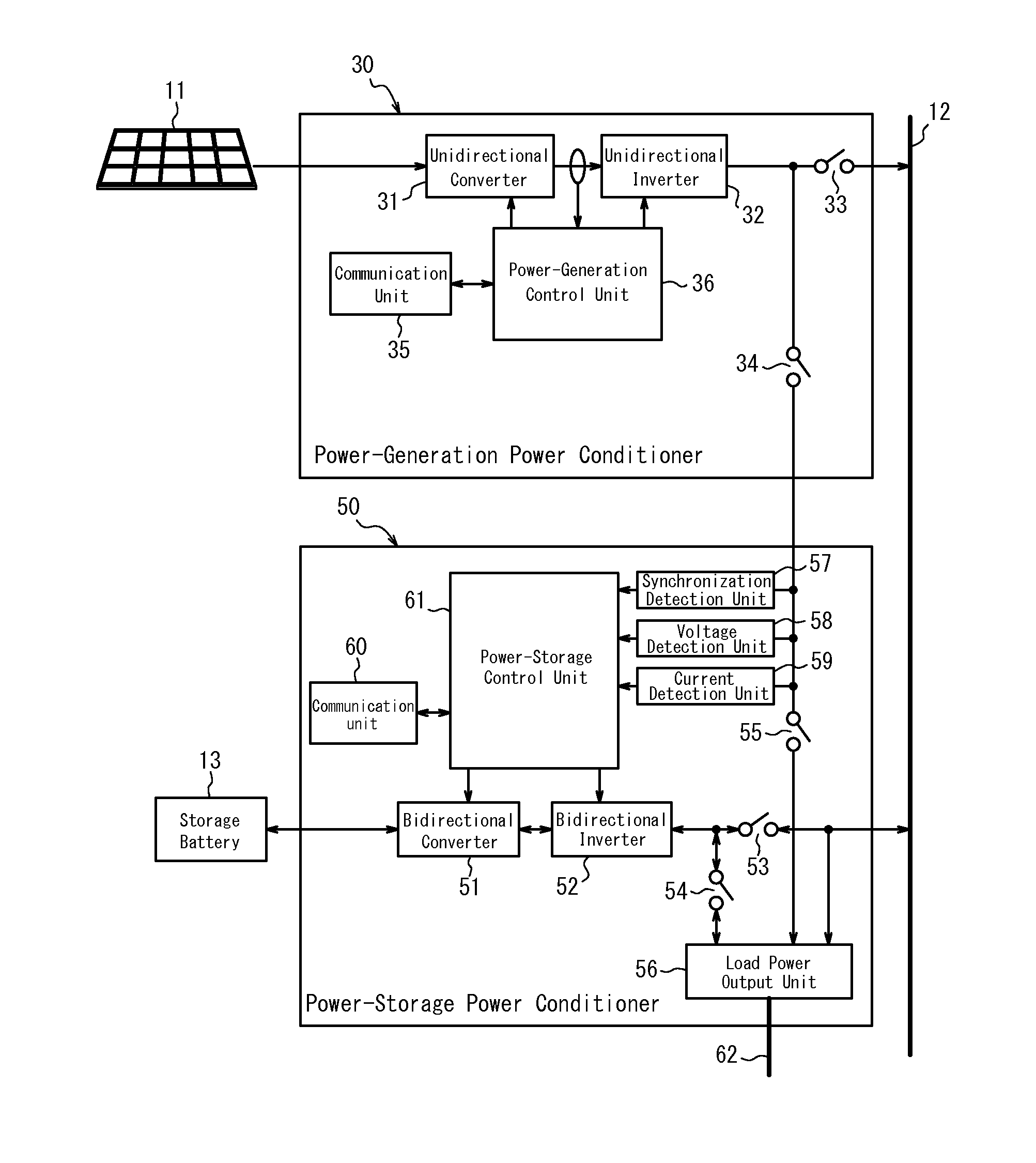
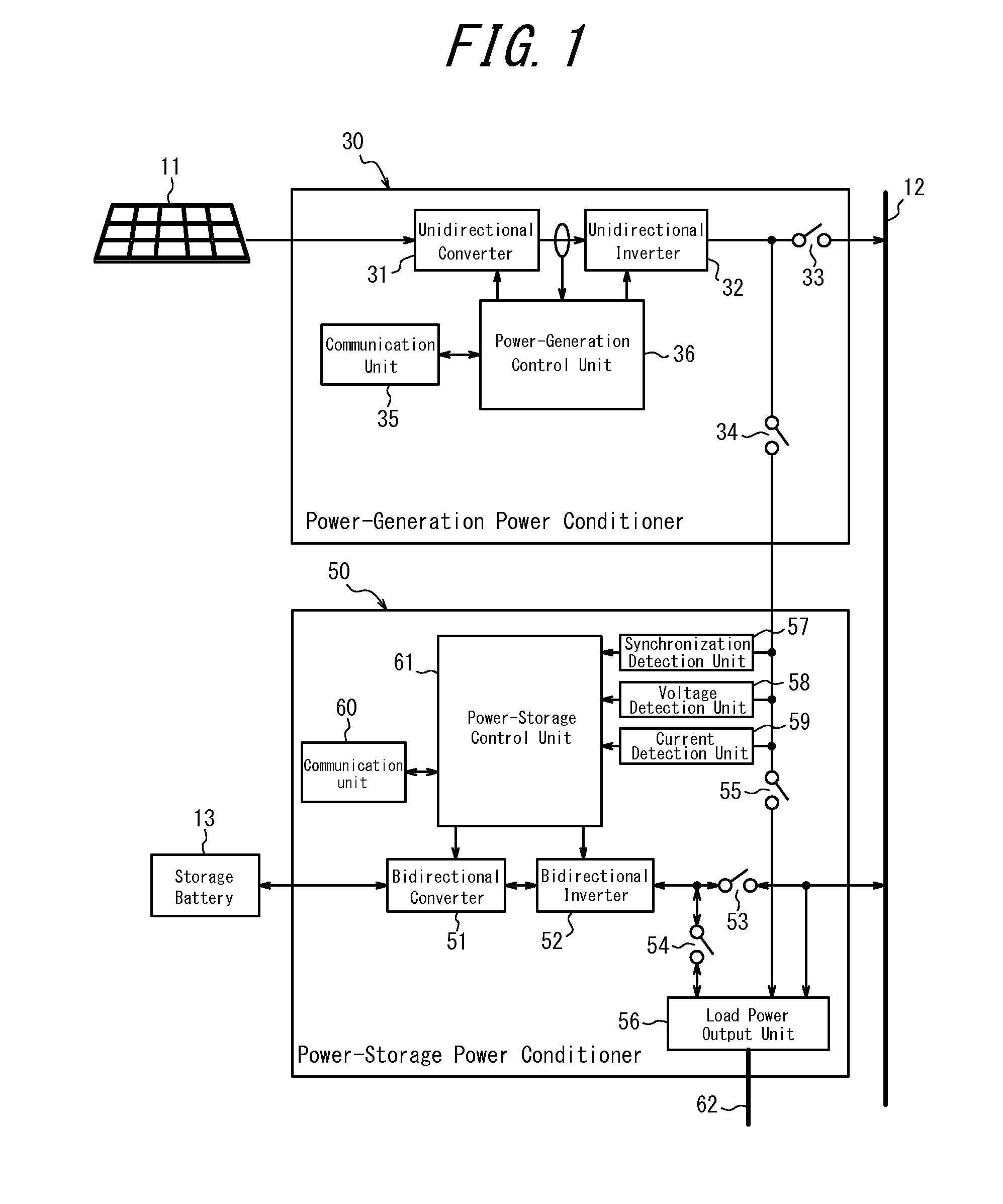
[0042]FIG. 1 is a block diagram illustrating a schematic configuration of a power conditioner system according to a first embodiment of the present invention. The power conditioner system according to the present embodiment includes a power-generation power conditioner 30 for connecting a power generation equipment 11 to a commercial power supply system (grid) 12 and a power-storage power conditioner 50 for connecting a power storage equipment 13 to the grid 12. Note that, according to the present embodiment, the power generation equipment 11 is configured by using a solar panel, and the power-generation power conditioner 30 is configured by using a solar power conditioner. Also, the power storage equipment 13 is configured by using a storage battery such as a lithium-ion battery, nickel-metal hydride battery or the like.

[0043]The power-generation power conditioner 30 includes a unidirectional converter 31, a unidirectional inverter 32, a system interconnection switch 33, an indepen...

second embodiment

[0072]FIG. 9 is a block diagram illustrating a schematic configuration of a section of a power conditioner system according to a second embodiment of the present invention. In the following description, components having the same effects as the components illustrated in FIG. 1 to FIG. 8 will be denoted with the same reference numerals. The power conditioner system according to the present embodiment has a configuration illustrated in FIG. 1, in which the DC power supplied from the unidirectional converter 31 of the power-generation power conditioner 30 to the unidirectional inverter 32 is selectively output, as a DC link output, from an independent output switch 81 corresponding to the independent-power-generation output unit to the power-storage power conditioner 50. Note that the independent output switch 81 serves also as a DC link switch. The independent output switch 81 may be replaced with a switch included in a section where the power is supplied to a unidirectional converter...


PUM


Abstract

A power conditioner system includes a power-generation power conditioner 30 for connecting a power generation equipment 11 to a grid 12 and a power-storage power conditioner 50 for connecting a power storage equipment 13 to the grid 12, wherein the power conditioner 30 includes an independent-power-generation output unit 34 for outputting, separately from power supply to the grid 12, power based on power of the power generation equipment 11, and the power conditioner 50 includes an independent-power-storage output unit 54 for outputting, separately from power supply to the grid 12, power based on power in the power storage equipment 13. The power conditioner 50 supplies at least one of AC power based on the output of the independent-power-generation output unit 34, AC power based on the output of the independent-power-storage output unit 54, and system power of the grid 12, to an independent output system 62 having a predetermined load.

Description

CROSS REFERENCE TO RELATED APPLICATION[0001]This application claims priority to and the benefit of Japanese Patent Application No. 2011-213081 filed on Sep. 28, 2011, the entire contents of which are incorporated herein by reference.FIELD[0002]The present invention relates to a power conditioner system, and more specifically, to a novel power conditioner system that includes a combination of a power-generation power conditioner of a power generation system and a power-storage power conditioner of a power storage system, and also to the power-storage power conditioner.BACKGROUND[0003]As a power-generation power conditioner of a power generation system including a power generation equipment such as solar panels and the like, there has been known a power conditioner that allows a system interconnection operation for outputting AC power by interconnecting with a commercial power supply grid-system (hereinafter, appropriately abbreviated as a grid) and an independent operation for output...

Claims


Application Information

Patent Timeline
IPC IPC(8): H02J7/34
CPCH02J7/34H02J7/35H02J3/32Y02E70/30H02J2203/20H02J2300/24H02J3/381Y02E10/56Y02E60/00Y04S40/20
Inventor OGUCHI, TOMIHIROKUSUNOSE, TOMONARISATAKE, MASAOMI
Owner KYOCERA CORP
Features
  • R&D
  • Intellectual Property
  • Life Sciences
  • Materials
  • Tech Scout
  • Unparalleled Data Quality
  • Higher Quality Content
  • 60% Fewer Hallucinations
Learn More