Coil actuator for a switching device and related switching device

a switching device and coil actuator technology, applied in the direction of relays, instruments, drug compositions, etc., can solve the problems of high installation cost, complicated wiring and cabling, and encumbrance due to the large volume occupied by additional equipment, and achieve the effect of high installation cost and complex wiring and cabling

Active Publication Date: 2014-08-07
ABB (SCHWEIZ) AG
View PDF7 Cites 7 Cited by
  • Summary
  • Abstract
  • Description
  • Claims
  • Application Information

AI Technical Summary

Problems solved by technology

The use of such external equipment implies a series of disadvantages, among which: complex wiring and cabling, high installation costs, and encumbrance due to the large volume occupied by the additional equipment.

Method used


Image

  • Coil actuator for a switching device and related switching device
  • Coil actuator for a switching device and related switching device
  • Coil actuator for a switching device and related switching device

Examples


Embodiment Construction

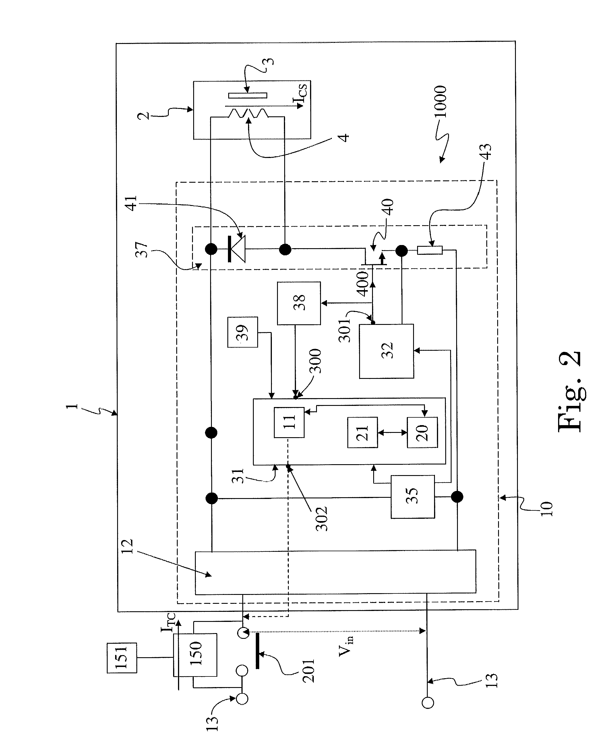
[0021]Exemplary embodiments of the present disclosure provide a coil actuator for an associated current switching device which can be actuated during its operation from an open position to a closed position to allow a current flowing therethrough and from the closed position to the open position to interrupt such current flowing.

[0022]The coil actuator including: a coil electromagnet arranged to move between a rest position and an actuating position, wherein the movement from the rest position to the actuating position is suitable to cause the actuation of the current switching device; electronic means arranged to count an operation time which is indicative of the duration of the actuation of the switching device.

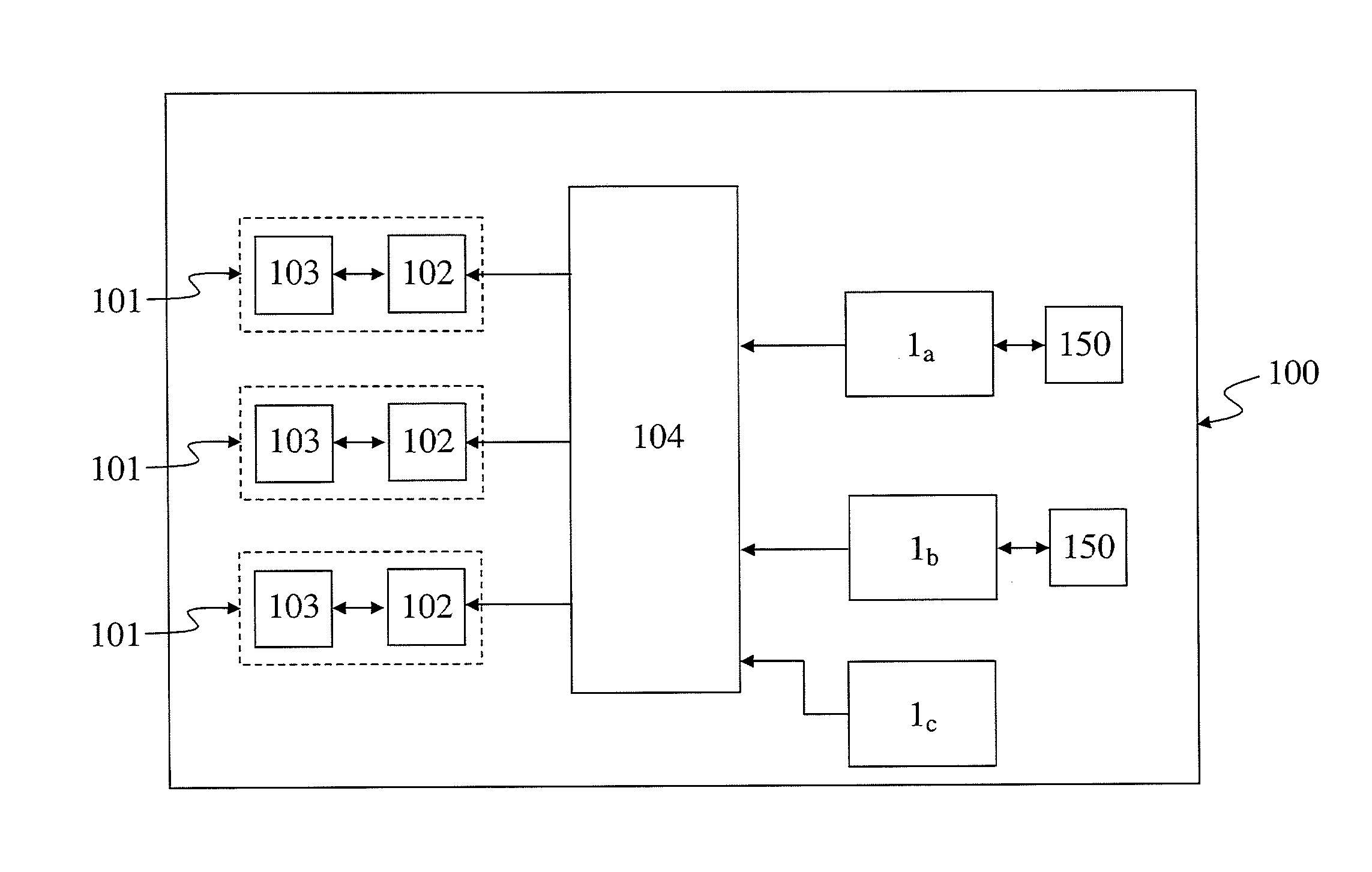
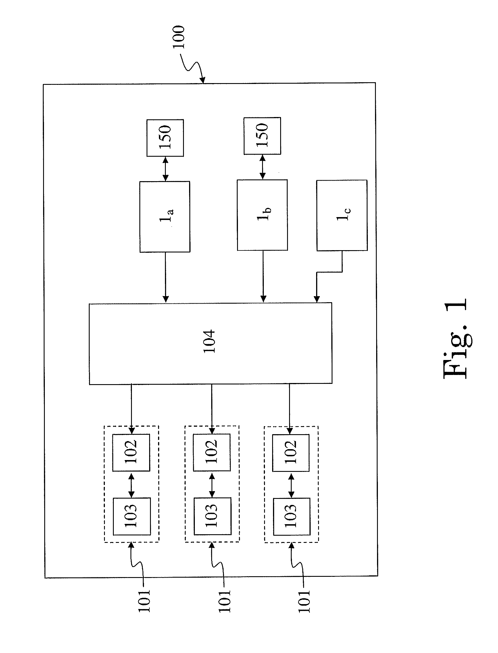
[0023]With reference to the exemplary embodiments of FIGS. 1-5, a coil actuator 1 according to the present disclosure is suitable for being installed in a switching device 100, such as for example a low or medium voltage circuit breaker 100, including at least a pole 101 ha...


PUM


Abstract

An exemplary coil actuator for an associated switching device which can be actuated during its operation from an open position to a closed position to allow a current to flow therethrough and from the closed position to the open position to interrupt such flowing from flowing therethrough. The coil actuator includes a coil electromagnet arranged to move between a rest position and an actuating position, wherein movement from the rest position to the actuating position is suitable to cause the actuation of the switching device; and an electronic component arranged to count an operation time which is indicative of the duration of the actuation of the switching device.

Description

RELATED APPLICATION[0001]This application claims priority as a continuation application under 35 U.S.C. §120 to PCT / EP2012 / 067448, which was filed as an International Application on Sep. 6, 2012 designating the U.S., and which claims priority to European Application 11184067.4 filed in Europe on Oct. 6, 2011. The entire contents of these applications are hereby incorporated by reference in their entireties.FIELD[0002]The present disclosure relates to a coil actuator for a switching device.BACKGROUND INFORMATION[0003]Known switching devices used in electrical circuits, such as in low or medium voltage electric circuits, such as circuit breakers, disconnectors and contactors, are devices designed to allow the correct operation of specific parts of the electric circuits in which they are installed, and of the associated electric loads. In the context of the present disclosure, the term “low voltage” is referred to applications with operating voltages up to 1000V AC / 1500V DC, and the te...

Claims


Application Information

Patent Timeline
Patent Type & Authority Applications(United States)
IPC IPC(8): H01H47/00
CPCH01H47/002H01H1/0015H01H83/06H01H83/12H01H2083/203A61P35/00G01R31/3278H01H47/10H01H50/00
Inventor MANNINO, FABIODE NATALE, GABRIELE VALENTINO
Owner ABB (SCHWEIZ) AG
Why Eureka
Try Eureka