System and device for acoustic measuring in a medium

a technology of acoustic measurement and a medium, applied in the direction of seismology for waterlogging, analysing solids using sonic/ultrasonic/infrasonic waves, instruments, etc., can solve the problem of inability to accurately determine the acoustic velocity in a fluid medium within a borehole during drilling, and the measurement of acoustic velocity is difficult to accurately determine the distan

Inactive Publication Date: 2014-08-07
PIEZO TECH
View PDF6 Cites 13 Cited by
  • Summary
  • Abstract
  • Description
  • Claims
  • Application Information

AI Technical Summary

Benefits of technology

[0008]In one form, a method according to the principles of the present invention, comprises providing a device having a measuring area, an acoustic transmitter situated in a first surface of the measuring area, the acoustic transmitter in communication with a processor, and an acoustic receiver situated in a second surface of the measuring area and non-parallel to the first surface, the acoustic receiver in communication with the processor, wherein at least one of the acoustic transmitter or the acoustic receiver has a plurality of acoustic elements, the acoustic transmitter is operable to emit a series of acoustic waveforms that result in one effective waveform in the media, and the acoustic receiver is operable to receive an acoustic signal that is a result of the unique individual acoustic waveforms from each element. The method including measuring via the processor, a time between when a predefined portion of one of the series of acoustic waveforms was emitted and when a predefined portion of the received acoustic signal corresponding to the predefined portion of one of the series of acoustic waveforms is received by the acoustic receiver, correlating via the processor, the measured time to a reference time of an acoustic waveform traveling in a known medium, the reference time corresponding to a velocity of sound in the known medium, and outputting via the processor, a correlation factor which may be used to determine the velocity of sound in the medium in the measuring area.

Problems solved by technology

Inaccuracy in the measurement of acoustic velocity translates into inaccuracy in the determination of distance.
Therefore, it is difficult to accurately determine acoustic velocity in a fluid medium within a bore hole during drilling.

Method used


Image

  • System and device for acoustic measuring in a medium
  • System and device for acoustic measuring in a medium
  • System and device for acoustic measuring in a medium

Examples


Embodiment Construction

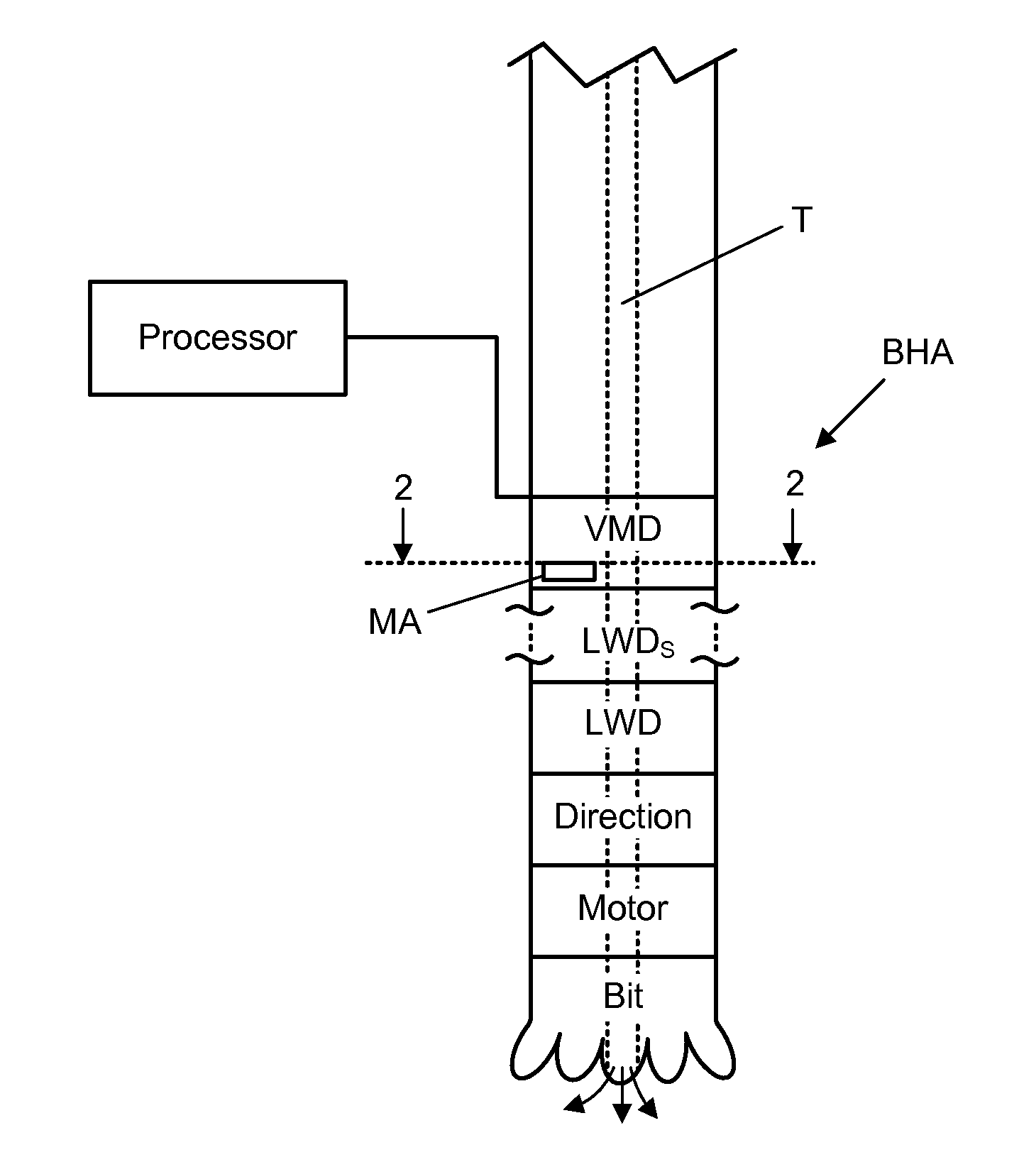
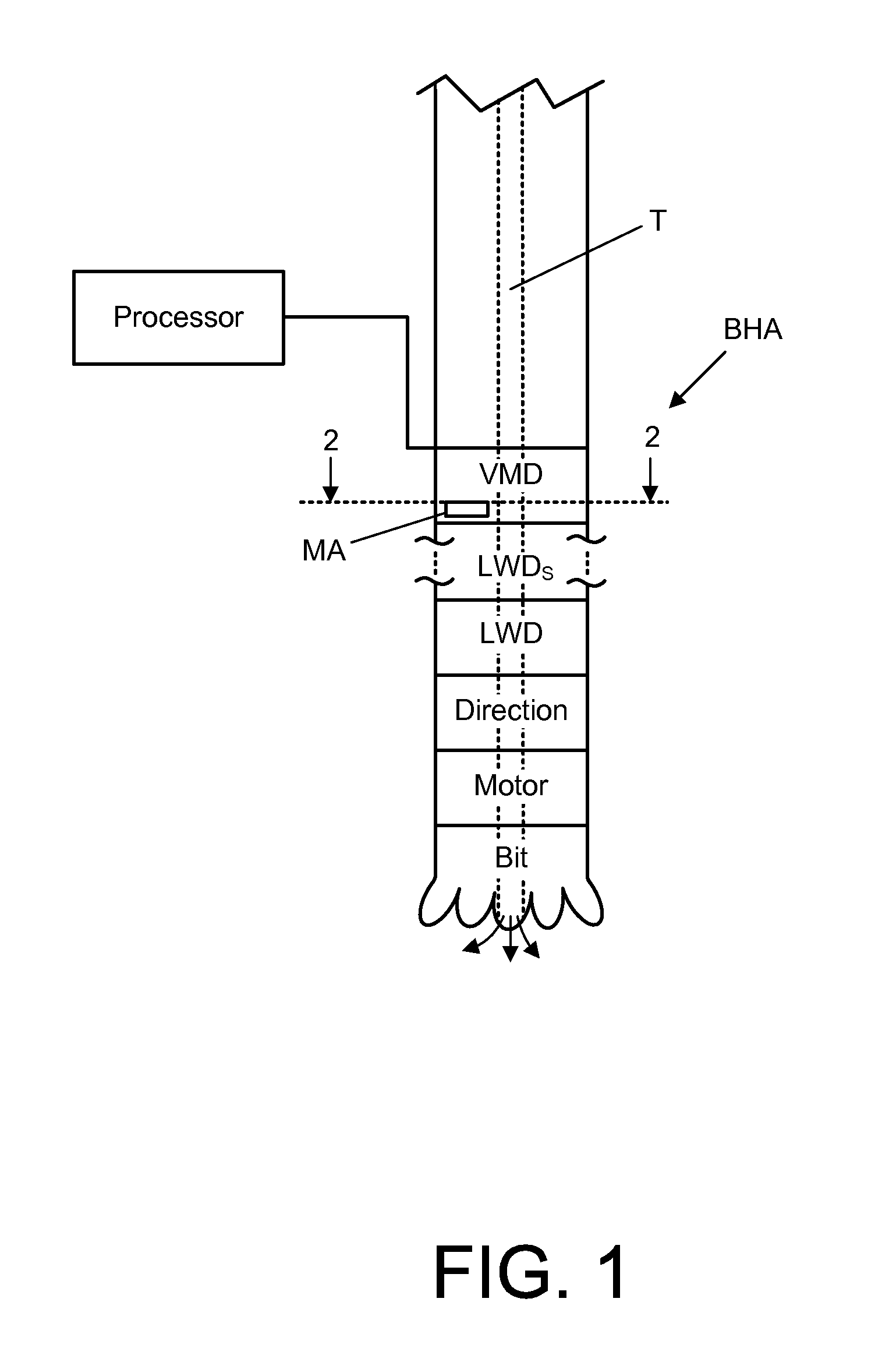
[0020]FIG. 1 illustrates an exemplary Bottom Hole Assembly (BHA) for a drilling operation having or incorporating the present velocity measuring device or tool (VMD) as provided herein. The BHA has a typical drill bit, motor, direction tool, one or more LWDs, and the present VMD. The components of the BHA, like the drilling pipe itself, are cylindrical, hollow, and threaded one each end in order to mount with pipe or BHA component (e.g. LWD, VMD or Direction), the outer diameter of the BHA components being less than that of the drill bit. Drilling mud is introduced through a tube or conduit T that extends from the surface of the bore hole to the BHA, with the tube T formed through the BHA components by their respective hollows. The drilling mud exits the tube T via the drill bit such that the mud flows around the drill bit, into and circulates upward through the bore hole (as represented by the arrows emanating from the end of drill bit) towards the surface of the bore hole. It shou...


PUM

PropertyMeasurementUnit
angleaaaaaaaaaa
angleaaaaaaaaaa
areaaaaaaaaaaa

Abstract

A device for acoustic measuring in a medium in a borehole such as velocity of sound in the medium or velocity of the medium, includes at least a first acoustic array situated in a first, slanted sidewall of a measuring area and operating to emit a series of acoustic waveforms across a measuring area. In one form, the device includes a second acoustic array situated in a second, slanted sidewall of the measuring area and operating to receive an acoustic signal resulting from the emitted series of acoustic waveforms or to receive said acoustic signal and emit a second series of acoustic waveforms. A the processor measures a time between when a predefined portion of one of the series of acoustic waveforms was emitted and when a predefined portion of the received acoustic signal corresponding to the predefined portion of one of the series of acoustic waveforms is received by the acoustic receiver, and correlates the measured time to a reference time, then outputs a correlation factor for determining the velocity of sound in the medium in the measuring area. The processor may also calculate transit time for the two emitted acoustic signals or echoes from the first emitted acoustic signals to determine medium flow velocity.

Description

FIELD OF THE INVENTION[0001]The present invention relates to the field of acoustic measurement devices and, more particularly, to devices for acoustic measuring in a medium.BACKGROUND[0002]Within the drilling industry, LWD (Logging While Drilling) devices have used acoustic pulse-echo measurements to measure a variety of parameters of a bore hole such as standoff, caliper, imaging and the like. These devices have one or more acoustic transducers that emit an acoustic pulse toward a surface being probed and then receive a reflected signal. Time between when the acoustic pulse is emitted and when a reflected signal is received (acoustic transit time) can then be used in the determination of distance. When the velocity of sound in a medium is known, acoustic transit time can be used to determine exact distance between the acoustic transducer and the surface being probed. Because the acoustic transducer of these devices is positioned such that at least some if not all of the acoustic si...

Claims


Application Information

Patent Timeline
Patent Type & Authority Applications(United States)
IPC IPC(8): G01N29/07
CPCG01N29/07G01V1/40G01N29/024G01N29/222G01N29/227G01N33/2823G01N2291/056G01N29/265G01N29/4427E21B47/107
Inventor DALLAS, JAMESLAUTZENHISER, FRANSMOLZ, ERIC
Owner PIEZO TECH
Why Eureka
Try Eureka