Printer apparatus and printer apparatus control method

Active Publication Date: 2014-08-07
FUJITSU COMPONENENT LTD
View PDF2 Cites 1 Cited by
  • Summary
  • Abstract
  • Description
  • Claims
  • Application Information

AI Technical Summary

Benefits of technology

[0010]According to an aspect of the present invention, a printer apparatus capable of print

Problems solved by technology

However, when measures are implemented to enable a printer apparatus to print on multiple sets of recording paper, the printer apparatus may be enlarged or the structure of

Method used


Image

  • Printer apparatus and printer apparatus control method
  • Printer apparatus and printer apparatus control method
  • Printer apparatus and printer apparatus control method

Examples


Example

First Embodiment

Printer Apparatus

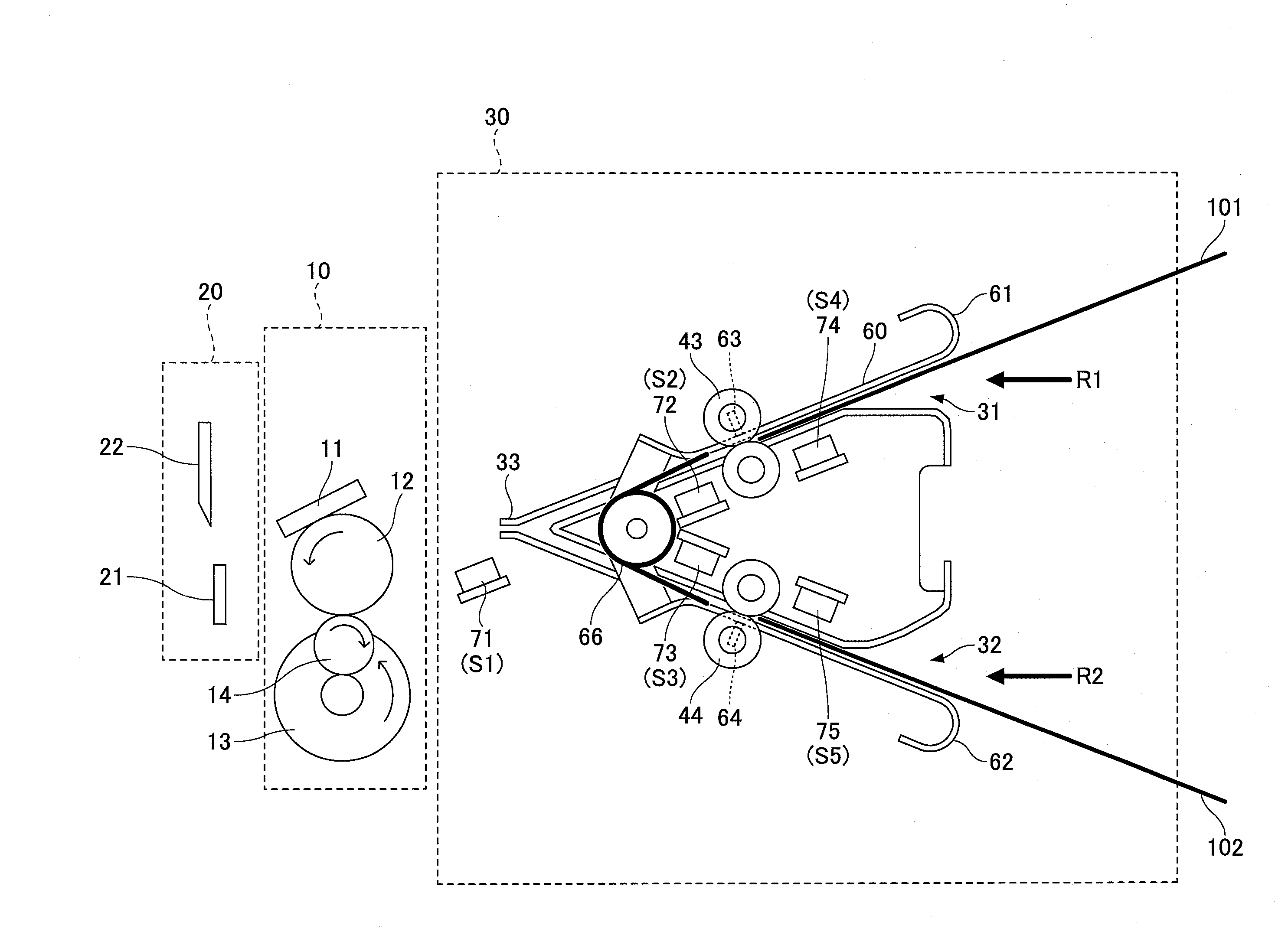
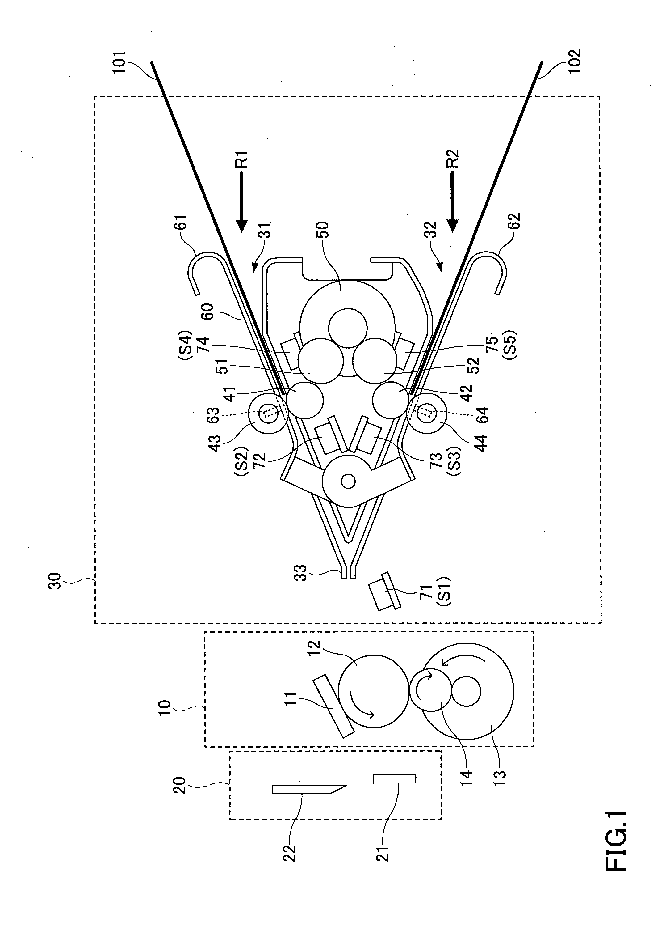
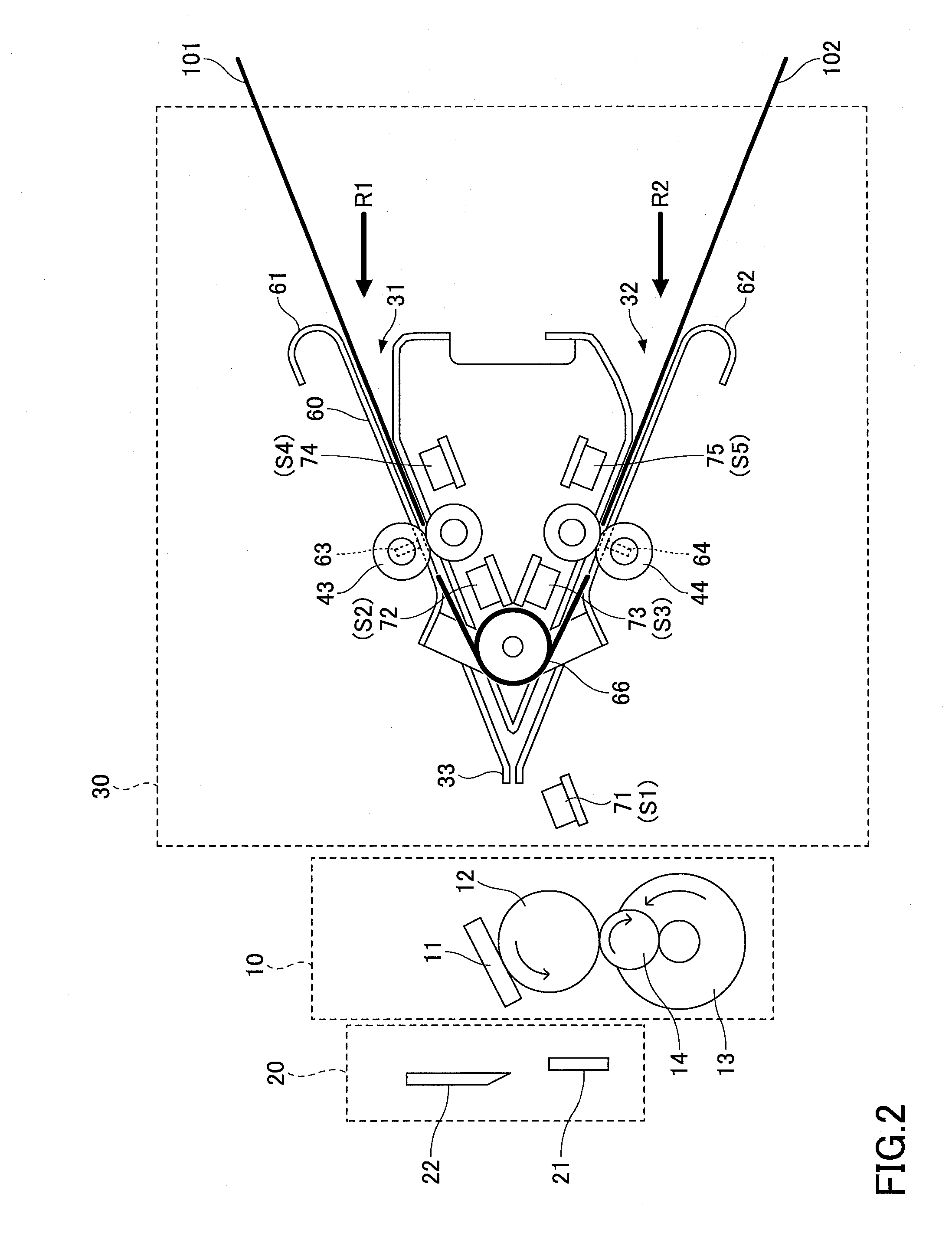
[0026]A printer apparatus according to a first embodiment of the present invention is described below. As illustrated in FIG. 1, the printer apparatus according to the first embodiment includes a printing part 10, a cutter part 20, and a recording paper feeding part 30 that is capable of feeding two different sets of recording paper to the printing part 10. Note that recording paper is an example of a recording sheet.

[0027]The printing part 10 includes a thermal head 11, a platen roller 12, a printing part motor 13, and a gear 14. The thermal head 11 is a print head for printing objects on recording paper. The thermal head 11 is configured to print objects on recording paper that is held between the thermal head 11 and the platen roller 12. The printing part motor 13 is a motor for rotating the platen roller 12 via the gear 14. When the printing part motor 13 is rotated, recording paper may be conveyed toward the cutter part 20. Note that although no...

Example

Second Embodiment

[0110]In the following, a second embodiment of the present invention is described. A printer apparatus according to the second embodiment includes a plurality of the recording paper feeding parts 30 described above, and a first feed port 31 or a second feed port 32 of one recording paper feeding part 30 is connected to a delivery port 33 of another recording paper feeding part 30.

[0111]For example, as illustrated in FIG. 14, the printer apparatus according to the present embodiment may include a first recording paper feeding part 130, a second recording paper feeding part 230, and a third recording paper feeding part 330, which have substantially the same configuration as the recording paper feeding part 30 described above and are cascade-connected. That is, a printing part 10 (not shown in FIG. 14) is connected to a delivery port 33 of the first recording paper feeding part 130, a second feed port 32 of the first recording paper feeding part 130 is connected to a d...


PUM

PropertyMeasurementUnit
Forceaaaaaaaaaa

Abstract

A printer apparatus includes a printing part including a platen roller and a print head for printing objects onto a recording sheet, and a feeding part for feeding the recording sheet to the printing part. The feeding part includes a first feed port and a second feed port for feeding the recording sheet, a first roller for conveying a first recording sheet fed through the first feed port, a second roller for conveying a second recording sheet fed through the second feed port, a delivery port for feeding the recording sheet conveyed by the first roller and the second roller, a tension member having elasticity, a third roller rotatably connected to the tension member and being pressed toward the first roller by the tension member, and a fourth roller rotatably connected to the tension member and being pressed toward the second roller by the tension member.

Description

CROSS-REFERENCE TO RELATED APPLICATIONS[0001]This patent application is based upon and claims the benefit of priority of Japanese Patent Application No. 2013-019845 filed on Feb. 4, 2013 the entire contents of which are incorporated herein by reference.BACKGROUND OF THE INVENTION[0002]1. Field of the Invention[0003]The present invention relates to a printer apparatus and a printer apparatus control method.[0004]2. Description of the Related Art[0005]Printers for issuing receipts are widely used in various applications including cash registers, Automated Teller Machines (ATM), and Cash Dispensers (CD), for example. Such printers are configured to issue a receipt by conveying a recording sheet such as thermal recording paper that is wound into a roll, printing objects such as characters on the recording sheet using a print head, and conveying the recording sheet up to a predetermined length so that the recording sheet may be cut at the predetermined length by a cutter (See, e.g., Japa...

Claims


Application Information

Patent Timeline
IPC IPC(8): B41J15/16
CPCB41J15/16B41J11/485B41J15/18G07B1/00B65H20/02B65H2301/4139B65H2404/1421B65H2404/143B65H2404/144
Inventor ISHIKAWA, TETSUHIROWATANABE, SUMIOMORI, YUKIHIROTSUCHIYA, MASAHIRO
Owner FUJITSU COMPONENENT LTD
Why Eureka
Try Eureka