Stereo endoscope apparatus and image processing method

a technology of endoscope and endoscope, which is applied in the field of stereo endoscope apparatus and image processing method, can solve the problems of difficult stereoscopy and weakening and achieve the effect of reducing the feeling of visual field interferen

Inactive Publication Date: 2014-08-07
CANON KK
View PDF0 Cites 3 Cited by
  • Summary
  • Abstract
  • Description
  • Claims
  • Application Information

AI Technical Summary

Benefits of technology

[0007]The present invention has been made in view of the above-mentioned problems. That is, the present invention may provide a stereo endoscope apparatus configured to perform, in a region causing a strong feeling of visual field interference, transparency-composition processing using an image in which a treatment instrument appears and an image in which the treatment instrument does not appear, thereby being capable of alleviating the feeling of visual field interference while an observer is recognizing the treatment instrument, and an image processing method thereof.

Problems solved by technology

In such stereo endoscope, for an object that is brought into close proximity with the stereo camera, such as the treatment instrument, a convergence angle determined by the stereo camera becomes too large, which makes stereoscopy difficult.
However, the hitherto known method involves determining a difficult region for the stereoscopy in advance and displaying only a monocular image for the region, or superimposing the mask image on the region.
Therefore, there is a problem in that, even though only a small part of the treatment instrument is delivered through the channel, the region other than the treatment instrument is also displayed as a two-dimensional image or masked.
Further, in the method disclosed in Japanese Patent Application Laid-Open No. 2012-223446, control is performed so that the tip portion of the treatment instrument is constantly visible, and hence, when this tip portion is located in the region difficult for the stereoscopy, the feeling of visual field interference may become stronger.

Method used


Image

  • Stereo endoscope apparatus and image processing method
  • Stereo endoscope apparatus and image processing method
  • Stereo endoscope apparatus and image processing method

Examples


first embodiment

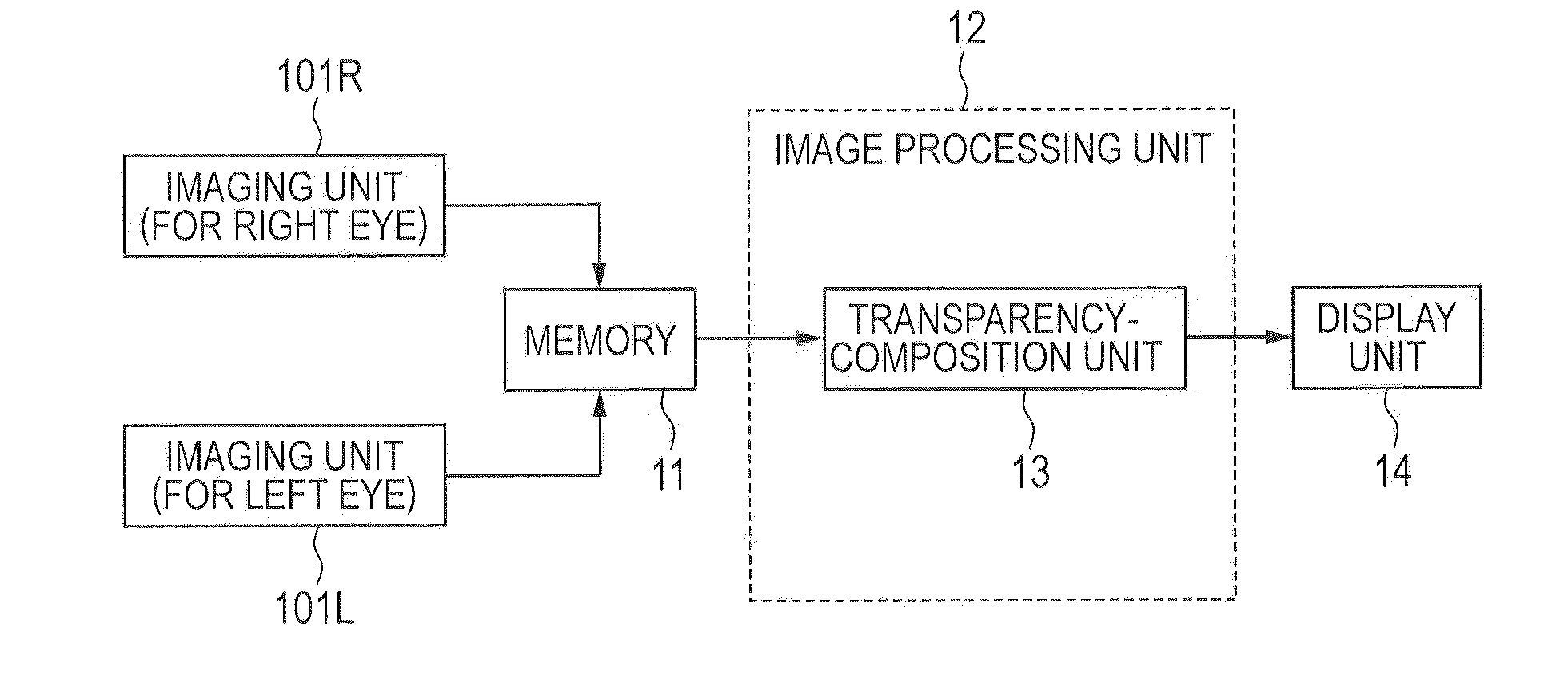
[0032]A stereo endoscope apparatus according to a first embodiment of the present invention is configured to perform, in a region causing a strong feeling of visual field interference, transparency composition using an image in which a treatment instrument appears and an image in which the treatment instrument does not appear. The transparency composition herein refers to image composition that involves blending the images at a predetermined composition ratio (blend ratio). An image H generated by performing the transparency composition using an image F and an image G can be expressed by the following equation (the image G is presumed as an image having the same pixel size as the image F). In the equation, “F(i,j)” represents a pixel value of the image F, “G(i,j)” represents a pixel value of the image G, “H(i,j)” represents a pixel value of the image H, and “transparency” represents a transparency ratio. Further, “i” and “j” are integer numbers satisfying 0

second embodiment

[0044]In a second embodiment of the present invention, the transparency-composition processing of the first embodiment is performed so that the tip of the treatment instrument is tracked and the range of a region in which the transparency-composition processing is performed and the composition ratio (transparency) are changed in accordance with the position of the tip.

[0045]FIG. 5 is a functional block diagram of a processing system according to this embodiment. FIG. 5 illustrates an imaging unit 102R for a right eye, an imaging unit 102L for a left eye, and a memory 51. Further, FIG. 5 illustrates an image processing unit 52 for processing images. The image processing unit 52 includes a tip-area detecting unit 53 for detecting a tip area of the treatment instrument within the images picked up by the imaging units, and also includes a transparency-composition unit 54. Further, FIG. 5 illustrates a display unit 55. The image processing unit 52 in this case may be realized through use...

third embodiment

[0054]In the first embodiment, the composition ratio of the transparency-composition processing is determined in advance. Alternatively, the observer may manually operate a slider switch and a volume switch to change the composition ratio in real time. Thus, in the initial stage of the operation of the treatment instrument, the observer may recognize the tip of the treatment instrument by increasing the composition ratio of the tip area of the treatment instrument within the observation screen, that is, by decreasing the transparency thereof. In the situation where the observer does not need to recognize the treatment instrument, the observer may decrease the composition ratio of the tip area of the treatment instrument, that is, increase the transparency thereof. In the case of inserting the treatment instrument through the channel, the observer needs to take care not to bring the treatment instrument into contact with an organ unintendedly, especially when delivering the tip of th...


PUM


Abstract

Provided is a stereo endoscope apparatus, including: a treatment instrument that is operable; at least two imaging units for picking up images of a subject; and a transparency-composition unit for performing, in a first region in which the treatment instrument appears within a first image picked up by one of the at least two imaging units, image composition by blending, at a predetermined composition ratio, an image of the first region and an image of a second region in which the treatment instrument does not appear within a second image picked up by another of the at least two imaging units.

Description

BACKGROUND OF THE INVENTION[0001]1. Field of the Invention[0002]The present invention relates to a stereo endoscope apparatus and an image processing method.[0003]2. Description of the Related Art[0004]A related-art stereo endoscope includes a stereo camera, a channel for inserting a treatment instrument, and a lighting device at a tip of the endoscope to be inserted into a subject to be observed. A doctor performs surgery using the treatment instrument and the like while observing a stereo image on a monitor.[0005]In such stereo endoscope, for an object that is brought into close proximity with the stereo camera, such as the treatment instrument, a convergence angle determined by the stereo camera becomes too large, which makes stereoscopy difficult. To address this problem, there have hitherto been known a method involving forming a two-dimensional image at only a predetermined area and a method involving generating and superimposing a mask image. Further, Japanese Patent Applicat...

Claims


Application Information

Patent Timeline
Patent Type & Authority Applications(United States)
IPC IPC(8): A61B1/00A61B1/05H04N13/122H04N13/239
CPCA61B1/05A61B1/00193G02B23/2415A61B1/00009G06T11/00A61B1/018H04N13/122H04N13/239H04N23/555
Inventor KATAYAMA, AKIHIRO
Owner CANON KK
Why Eureka
Try Eureka