Dehumidification system for air conditioning

a technology of air conditioning and humidification system, which is applied in the direction of domestic cooling apparatus, heating types, separation processes, etc., can solve the problems of increasing the maintenance cost inefficient process, and inconvenient use of the air conditioning system

Active Publication Date: 2014-08-14
CARRIER CORP
View PDF7 Cites 43 Cited by
  • Summary
  • Abstract
  • Description
  • Claims
  • Application Information

AI Technical Summary

Benefits of technology

[0012]FIG. 1 is a schematic diagram of an air temperature and hum

Problems solved by technology

Conventional air conditioning systems generally do not perform humidity control functions.
Significant energy is consumed during the supercooling and reheating, which renders the process inefficient.
Moreover, water condensation on metallic DX coils may cause corrosion problems, which adds to the maintenance cost of the air conditioning systems.
While capable of achieving low humidity outputs, systems based on desiccant wheels may be space-consuming and may suffer from lack of efficiency, as heating energy is required to regenerate the desiccant.
Moreover, because the desiccant wheel is relatively cumbersome and not easy to install or uninstall, the capacity and operation of the systems based on

Method used


Image

  • Dehumidification system for air conditioning
  • Dehumidification system for air conditioning
  • Dehumidification system for air conditioning

Examples


Embodiment Construction

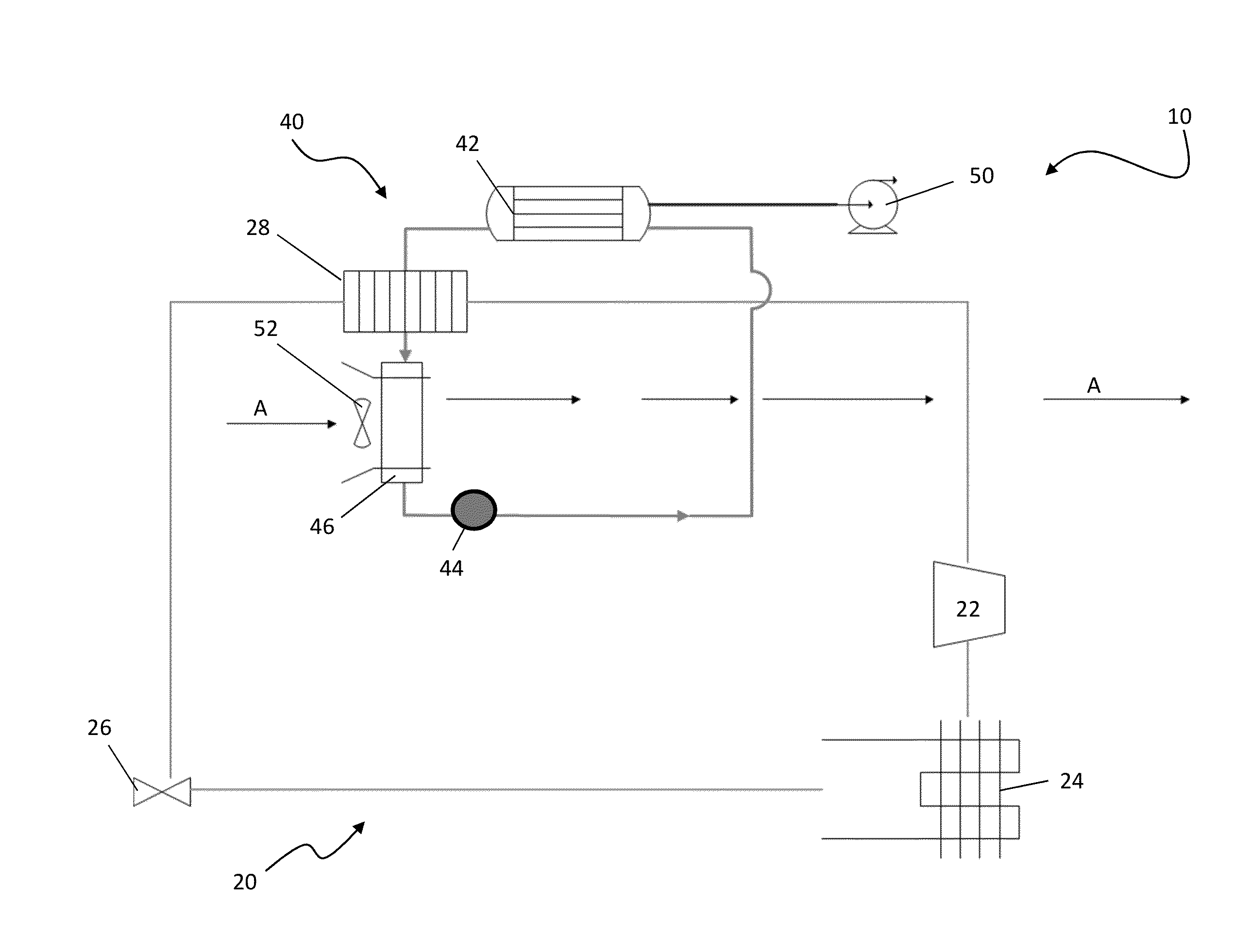
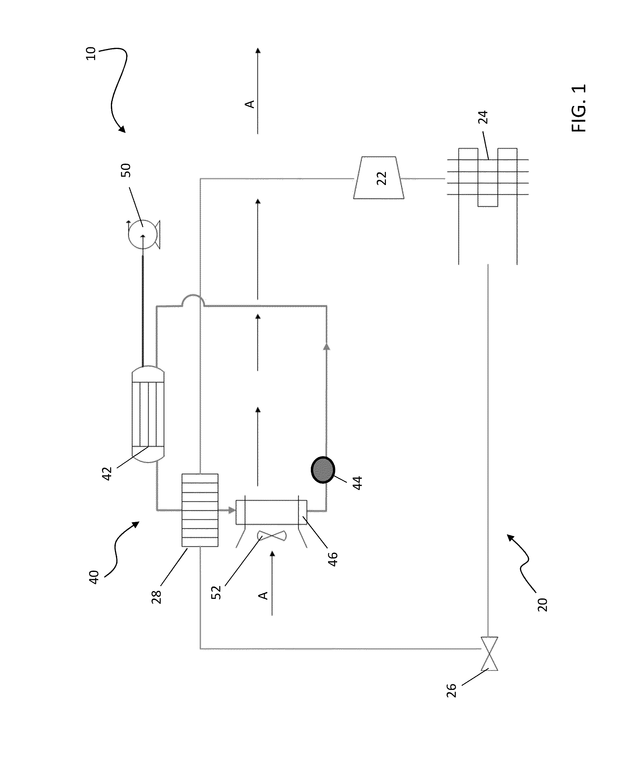
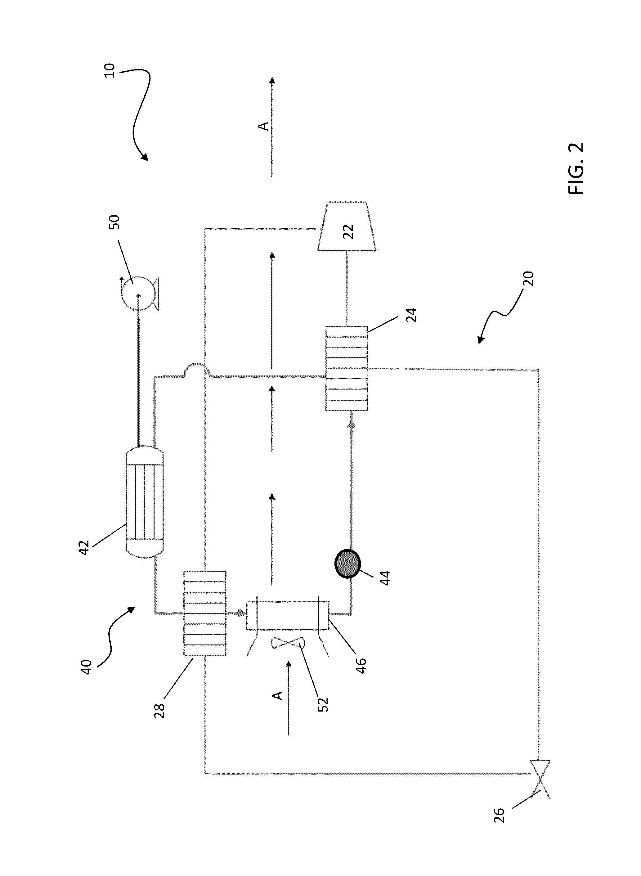
[0016]Referring now to the FIGS., an air temperature and humidity control device 10 includes a heat pump 20 and a humidity controller 40. The heat pump 20 includes a compressor 22, a condenser 24, an expansion valve 26, and an evaporator 28. In operation, a refrigerant R is circulated through the various components of the heat pump 20 in a known manner so that the refrigerant R is in a compressed state (releasing heat) in the condenser 24 and is in an expanded state (heat absorbing) in the evaporator 28. The refrigerant R is an environmentally friendly refrigerant based on R-410; however other refrigerants are within the scope of the invention.

[0017]The humidity controller 40 may include a first contactor 42 through which a liquid desiccant LD flows, such as an aqueous lithium chloride solution for example. Other hygroscopic liquid substances may also be used as the liquid desiccant and should be considered as within the scope of this invention. In one embodiment, the first contacto...


PUM


Abstract

An air temperature and humidity control device is provided including a heat pump and a humidity controller. The heat pump has a condenser, a first evaporator, a compressor, and a second evaporator. The humidity controller includes a first contactor fluidly coupled to the second evaporator. The first contactor includes at least one contact module having a porous sidewall that defines an internal space through which a liquid desiccant flows. A liquid source is coupled to the first contactor such that a second liquid provided by the liquid source flows through the first contactor adjacent an external side of the porous sidewall. Heat and/or water vapor transfers between the second liquid and the liquid desiccant.

Description

CROSS-REFERENCE TO RELATED APPLICATIONS[0001]This application claims the benefit of U.S. provisional patent application Ser. No. 61 / 764,311 filed Feb. 13, 2013, the entire contents of which are incorporated herein by reference.BACKGROUND OF THE INVENTION[0002]The invention relates generally to an air temperature and humidity control device, and more particularly, to an air temperature and humidity control device including a liquid-liquid contactor.[0003]Conventional air conditioning systems generally do not perform humidity control functions. In case humidity control is desired, air conditioners based on direct expansion (DX) may be operated to condense moisture in the air through supercooling. The drier, supercooled air is then reheated for comfort before entering into a facility to be air conditioned. Significant energy is consumed during the supercooling and reheating, which renders the process inefficient. Moreover, water condensation on metallic DX coils may cause corrosion pro...

Claims


Application Information

Patent Timeline
IPC IPC(8): F25D17/04B01D53/14
CPCF25D17/042B01D53/1425B01D53/263F24F2003/1435B01D53/26Y10T137/87571F24F5/001F24F3/1417
Inventor RANJAN, RAJIVWINCH, GARY D.
Owner CARRIER CORP
Why Eureka
Try Eureka