Drive unit for aircraft running gear wheels

Inactive Publication Date: 2014-08-14
L 3 COMM MAGNET MOTOR
View PDF3 Cites 59 Cited by
  • Summary
  • Abstract
  • Description
  • Claims
  • Application Information

AI Technical Summary

Benefits of technology

[0006]Accordingly, the problem underlying the present invention is to provide a drive for an aircraft running gear that allows for supp

Problems solved by technology

As the gas turbine engines of airplanes are not designed to operate efficiently in a low power state, such as needed during the taxiing operation on the ground, maneuvering of the aircraft on the ground consumes a lot of fuel.
Increasing fuel prices have made this fuel consumption during taxiing more and more worrisome.
However, since such special vehicles are expensive themselves and not available in large numbers at most airports, they are commonly only used for short distances, suc

Method used


Image

  • Drive unit for aircraft running gear wheels
  • Drive unit for aircraft running gear wheels
  • Drive unit for aircraft running gear wheels

Examples


first embodiment

[0094]Each of the first and second sprocket elements 108 and 110 is a ring-like structure having on its outer side two adjacent rows of sprocket teeth arranged along the perimeter of the respective sprocket element. Each of the first and second sprocket elements 108 and 110 is fixedly coupled to the rim of the respectively associated wheel 2 or 4. As described above with the first embodiment, each one of the sprocket elements 108 and 110 can either be coupled rigidly to the respective rim in a suitable manner or can be manufactured as one piece together with the respective rim. In any case, it is ensured that a turning of the sprocket elements leads to a turning of the associated wheels. It is also possible that the sprocket elements are not ring-like structures, but disk-like structures.

[0095]Each of the first and second power output assemblies 122 and 124 is an arm-like structure that is coupled to the gearbox 26 at one of its ends. For each of the first and second power output as...

third embodiment

[0099]The operation of the aircraft running gear 2 is described as follows. When the aircraft having the aircraft running gear 2 does not need the drive unit 16 to drive the aircraft, such as during dragging or pushing of the aircraft by a special vehicle or during take-off or landing, the first and second power output assemblies 122 and 124 are in the positions of disengagement shown in FIG. 7a. The two wheels (not shown) can rotate independently from the drive unit 16. When driving the aircraft via the aircraft running gear 2 is desired, such as during taxiing, the two power output assemblies 122 and 124 are rotated to be in the position of engagement, as shown with respect to the first power output assembly 122 in FIG. 7b. The power transmission chains of the power output assemblies 122 and 124 are driven by the first and second motors 18 and 20 via the gearbox 26, such that the power transmission chains transfer the driving power to the first and second sprocket elements 108 an...


PUM


Abstract

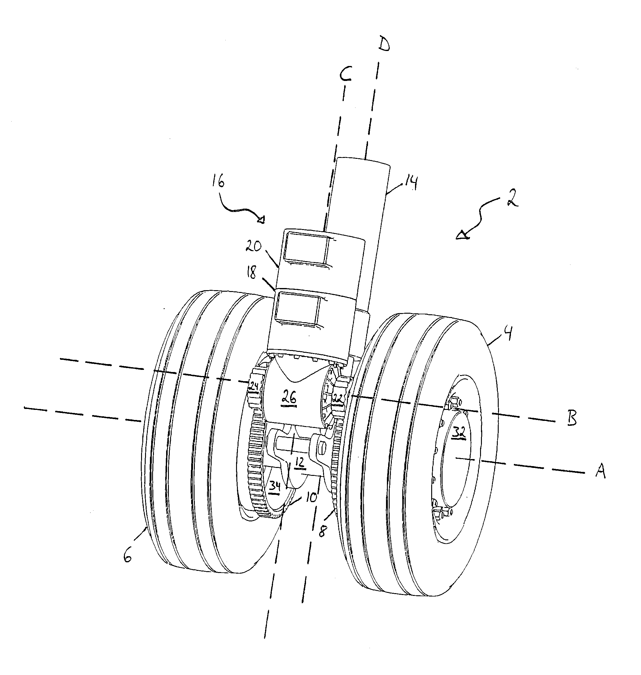
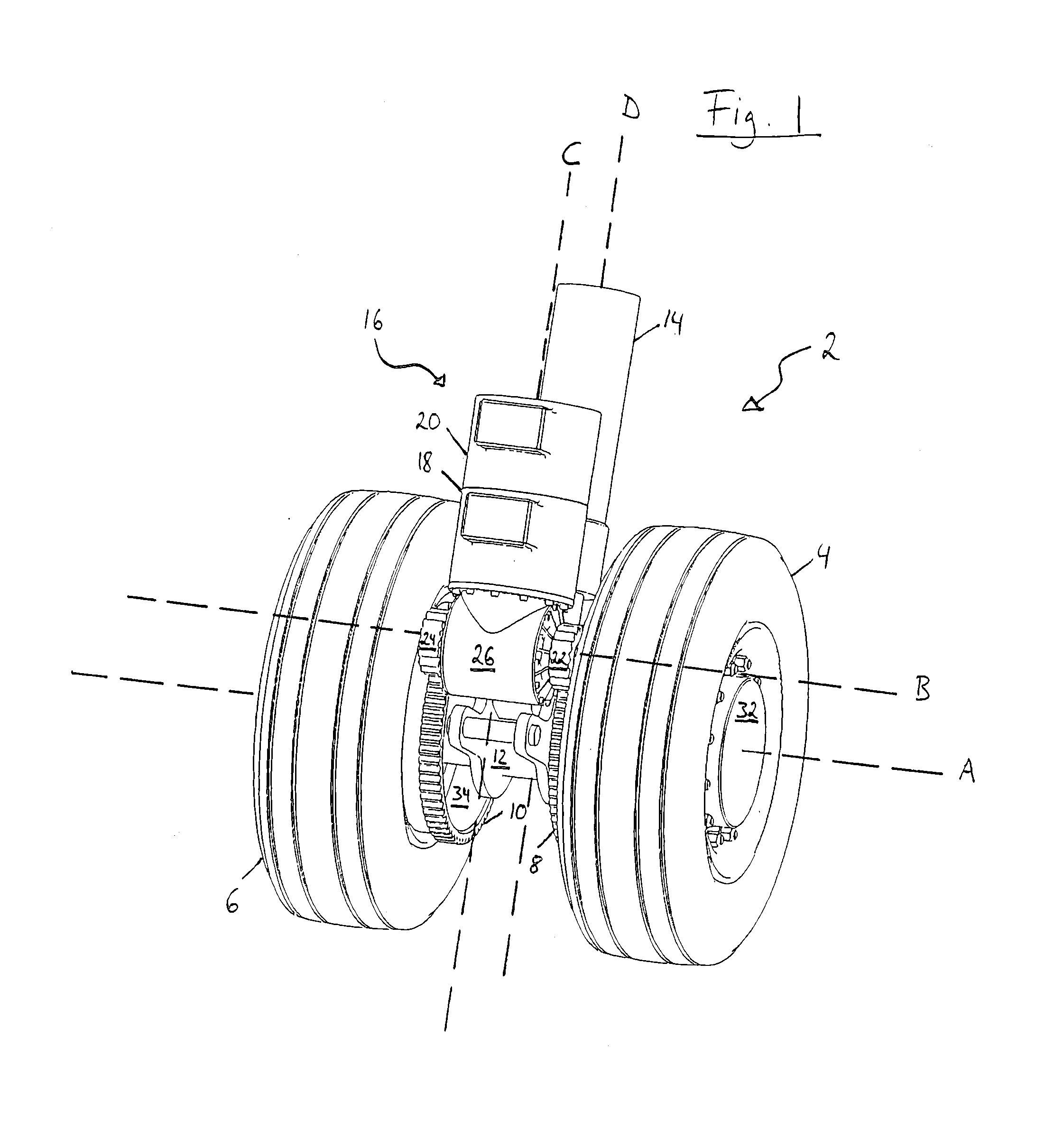
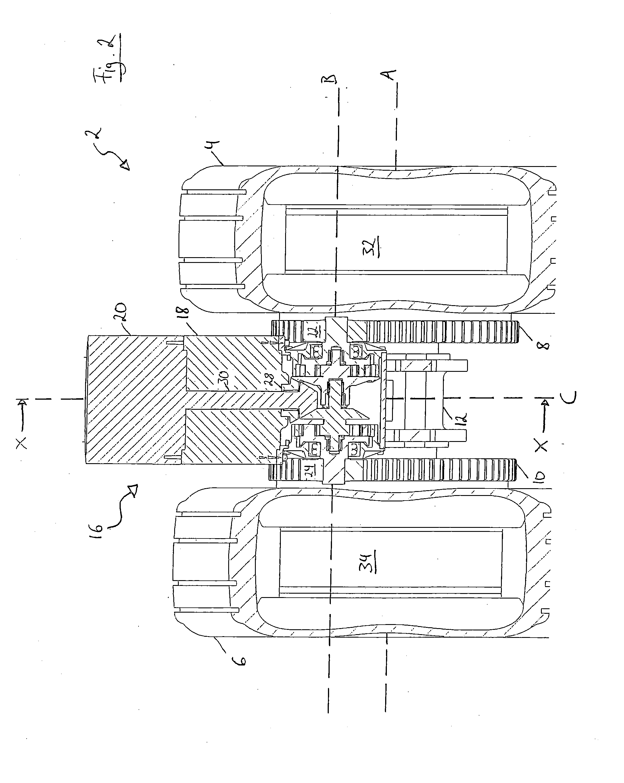
A drive unit (16) for an aircraft running gear (2) having at least a first wheel (4) and a second wheel (6) on a common wheel axis (A), wherein the drive unit (16) is drivingly coupleable to at least one of the first and second wheels (4, 6), is characterized in that the drive unit (16) comprises at least one power output assembly (122, 124) for driving at least one of the first and second wheels (4, 6), with each of the at least one power output assembly (122, 124) comprising a power transmission chain (136) selectively engageable with a sprocket element (108, 110) coupled to one of the first and second wheels (4, 6).

Description

RELATED APPLICATIONS[0001]The present application claims the benefit under 35 U.S.C. §371 of International Patent Application No. PCT / EP / 2011 / 060172, having an internal filing date of Jun. 17, 2011, the content of which is incorporated herein by reference in its entirety.FIELD OF THE INVENTION[0002]The present invention is directed to a drive unit for an aircraft running gear and to an aircraft running gear comprising a drive unit.BACKGROUND ART[0003]Conventionally, large commercial aircraft, also referred to as airplanes hereinafter, use their gas turbine engines to taxi on an airfield or maneuvering area of an airport. As the gas turbine engines of airplanes are not designed to operate efficiently in a low power state, such as needed during the taxiing operation on the ground, maneuvering of the aircraft on the ground consumes a lot of fuel. Increasing fuel prices have made this fuel consumption during taxiing more and more worrisome. Moreover, the fuel efficiency for the whole fl...

Claims


Application Information

Patent Timeline
IPC IPC(8): B64C25/40
CPCB64C25/405B60K2007/003Y02T50/80B64C5/02
Inventor OSWALD, JOHANNHEEG, MANFRED
Owner L 3 COMM MAGNET MOTOR
Why Eureka
Try Eureka